Table of Contents
Advertisement
Quick Links
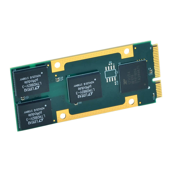
AP513 AcroPack
Isolated RS-232 Serial Communication Module
USER'S MANUAL
ACROMAG INCORPORATED
30765 South Wixom Road
Wixom, MI 48393-2417 U.S.A.
Tel: (248) 295-0310
Email: solutions@acromag.com
Copyright 2019, Acromag, Inc., Printed in the USA.
Data and specifications are subject to change without notice.
8501146B
Advertisement
Table of Contents

Related Manuals for Acromag AcroPack AP513


Summary of Contents for Acromag AcroPack AP513
- Page 1 Isolated RS-232 Serial Communication Module USER’S MANUAL ACROMAG INCORPORATED 30765 South Wixom Road Wixom, MI 48393-2417 U.S.A. Tel: (248) 295-0310 Email: solutions@acromag.com Copyright 2019, Acromag, Inc., Printed in the USA. Data and specifications are subject to change without notice. 8501146B...
-
Page 2: Table Of Contents
2.4 Field I/O Connector ....................10 Table 2.1 Field I/O Connector Pin Assignments ................11 2.5 Isolation ........................14 2.6 Logic Interface Connector ................... 14 Table 2.2 Logic Interface Connections ..................14 Acromag, Inc. Tel: 248-295-0310 - 1 - - 1 - www.acromag.com http://www.acromag.com... - Page 3 Table 3.9 Typical Data Rates with Internal 125MHz Clock at 16X Sampling ....... 30 3.4.3.2 DLD[7:4] ......................... 30 Table 3.10 DLD Register[7:4] ....................... 30 3.4.4 Interrupt Enable Register (IER) – Read/Write ................31 Acromag, Inc. Tel: 248-295-0310 - 2 - - 2 - www.acromag.com...
- Page 4 4.1 Service and Repair Assistance ..................49 4.2 Preliminary Service Procedure ..................49 4.3 Where to Get Help ...................... 49 5.0 SPECIFICATIONS ......................50 5.1 Physical ........................50 Acromag, Inc. Tel: 248-295-0310 - 3 - - 3 - www.acromag.com http://www.acromag.com...
- Page 5 Table 5.4 MTBF ..........................51 5.5 PCIe Bus Specifications ....................52 APPENDIX A .......................... 53 AP-CC-01 Heatsink Kit Installation ..................53 CERTIFICATE OF VOLATILITY ..................56 REVISION HISTORY ......................57 Acromag, Inc. Tel: 248-295-0310 - 4 - - 4 - www.acromag.com http://www.acromag.com...
-
Page 6: General Information
The information contained in this manual is subject to change without notice, and Acromag, Inc. (Acromag) does not guarantee its accuracy. Acromag makes no warranty of any kind with regard to this material, including, but not limited to, the implied warranties of merchantability and fitness for a particular purpose. -
Page 7: Acropack Information - All Models
Analog Devices LTM2882 Dual Isolated RS232 µModule Transceiver + Power, so isolated power does not need to be supplied externally. • 16550 compatible – Exar Quad UART with 16550-compatible register set. Acromag, Inc. Tel: 248-295-0310 - 6 - - 6 - www.acromag.com http://www.acromag.com... -
Page 8: Key Features Pcie Interface
Compatibility – PCI Express Base Specification v2.0 compliant PCI Express Endpoint. 1.4 Signal Interface Products This AcroPack module will mate directly to all Acromag AP carriers. Once connected, the module is accessed via a front panel connector. The cables and termination panels are also available. For optimum performance with the AP513 communication module, use of the shortest possible length of shielded I/O cable is recommended. -
Page 9: Software Support
AcroPack modules, VPX I/O board products, and PCIe I/O Cards. The software is implemented as a library of “C” functions which link with existing user code to make possible simple control of all Acromag AcroPack modules. 1.6 References The following resources regarding AcroPack modules are available for download on Acromag’s website or by contacting your sales representative. -
Page 10: Preparation For Use
It is important that the user employ satisfactory overall system design. It is understood and agreed by the Buyer and Acromag that this is the Buyer's responsibility. -
Page 11: Installation Considerations
Refer to the specifications section for loading and power requirements. Be sure that the system power supplies are able to accommodate the power IMPORTANT: Adequate air requirements of the system boards, plus the installed Acromag board, circulation must be provided to within the voltage tolerances specified. - Page 12 RSVD/ISOL RSVD/ISOL RSVD/ISOL Field I/O 12 RXD_B RSVD/ISOL RSVD/ISOL RSVD/ISOL Field I/O 14 TXD_B RSVD/ISOL RSVD/ISOL RSVD/ISOL Field I/O 16 CTS_B* RSVD/ISOL RSVD/ISOL RSVD/ISOL Field I/O 18 RTS_B* Acromag, Inc. Tel: 248-295-0310 - 11 - - 11 - www.acromag.com http://www.acromag.com...
- Page 13 RSVD/ISOL RSVD/ISOL RSVD/ISOL Field I/O 30 TXD_C RSVD/ISOL RSVD/ISOL RSVD/ISOL Field I/O 32 CTS_C* RSVD/ISOL RSVD/ISOL RSVD/ISOL Field I/O 34 RTS_C* RSVD/ISOL RSVD/ISOL Field I/O 35 Isolated GND_D Acromag, Inc. Tel: 248-295-0310 - 12 - - 12 - www.acromag.com http://www.acromag.com...
- Page 14 Field I/O 43 RTS_D* RSVD/ISOL RSVD/ISOL RSVD/ISOL RSVD/ISOL RSVD/ISOL RSVD/ISOL RSVD/ISOL RSVD/ISOL RSVD/ISOL RSVD/ISOL RSVD/ISOL RSVD/ISOL RSVD/ISOL RSVD/ISOL RSVD/ISOL Note: An asterisk (*) is used to indicate an active-low signal. Acromag, Inc. Tel: 248-295-0310 - 13 - - 13 - www.acromag.com http://www.acromag.com...
-
Page 15: Isolation
TDI (UIM_C4) N.C. (W_DISABLE#) TDO (UIM_C8) N.C. (UIM_VPP) RECLK+ N.C. (UIM_RESET) REFCLK- N.C. (UIM_CLK) N.C. (UIM_DATA) N.C. (CLKREQ#) N.C. (UIM_PWR) N.C. (TCK) [COEX2] N.C. (+1.5V) N.C. (TMS) [COEX1] Acromag, Inc. Tel: 248-295-0310 - 14 - - 14 - www.acromag.com http://www.acromag.com... - Page 16 AP513 module. Note 6: TDI is tied to TDO on the AP513 module as it does not use JTAG. Acromag, Inc. Tel: 248-295-0310 - 15 - - 15 - www.acromag.com...
-
Page 17: Programming Information
The Configuration Registers are accessed via the Configuration Address and Data Ports. The most important Configuration Registers are the Base Address Registers and the Interrupt Register which must be read to Acromag, Inc. Tel: 248-295-0310 - 16 - - 16 - www.acromag.com... -
Page 18: Uart And Device Configuration Registers
The Device Configuration Registers are accessible from all UART channels, however not all bits can be controlled by all channels. The control of the 8XMODE, 4XMODE, RESET, and SLEEP bits are only available for that particular channel. Acromag, Inc. Tel: 248-295-0310 - 17 - - 17 - www.acromag.com... - Page 19 Read/Write MPIO[7:0] level 0x00 control 0x091 MPIO3T[7:0] Not Used. 0x00 0x092 MPIOINV[7:0] Not Used. 0x00 0x093 MPIOSEL[7:0] Not Used. 0XFF 0x094 MPIOOD[7:0] Not Used. 0x00 0x095 MPIOINT[15:8] Not Used. 0x00 Acromag, Inc. Tel: 248-295-0310 - 18 - - 18 - www.acromag.com http://www.acromag.com...
-
Page 20: The Global Interrupt Registers - Int0, Int1, Int2 And Int3
If there is a global interrupt such as the wake-up interrupt, timer/counter interrupt or MPIO interrupt, then they would be reported in the 3-bit code for channel 0 Acromag, Inc. Tel: 248-295-0310 - 19 - - 19 - www.acromag.com... -
Page 21: Interrupt Clearing
TIMER Time-out interrupt clears after reading the TIMERCNTL register that is in the Device Configuration register set. • MPIO interrupt clears after reading the MPIOLVL register that is in the Device Configuration register set. Acromag, Inc. Tel: 248-295-0310 - 20 - - 20 - www.acromag.com http://www.acromag.com... -
Page 22: General Purpose 16-Bit Timer/Counter [Timermsb, Timerlsb, Timer, Timecntl]
Re-triggerable mode selected • Internal 125MHz clock selected as clock source • Timer output not routed to MPIO[0] • Timer stopped Table 3.6 Timer Control Register TIMERCNTL[7:4] Reserved Acromag, Inc. Tel: 248-295-0310 - 21 - - 21 - www.acromag.com http://www.acromag.com... -
Page 23: Timer Operation
Timer does not have any effect in re-triggerable mode. The Timer must be programmed while it is stopped since the following operations are blocked when the Timer is running: Acromag, Inc. Tel: 248-295-0310 - 22 - - 22 - www.acromag.com... -
Page 24: 8Xmode[7:0] (Default 0X00)
RESET register in channel 0 will only reset channel 0. Each bit is self-clearing after it is written a logic 1 to perform a reset to that channel. All registers in that channel will be reset to the default condition. Acromag, Inc. Tel: 248-295-0310 - 23 - - 23 - www.acromag.com... -
Page 25: Sleep[31:24] (Default 0X00)
REGB register provides a control for simultaneous write to all 4 UARTs configuration register or individually. This is very useful for device initialization in the power up and reset routines. Table 3.7 REGB Register REGB[23:19] Not Used. Acromag, Inc. Tel: 248-295-0310 - 24 - - 24 - www.acromag.com http://www.acromag.com... -
Page 26: Mpio Registers
16550 compatible so their access is limited to 8-bit format. The software driver must separately read the LSR content for the associated error flags before reading the data byte. Acromag, Inc. Tel: 248-295-0310 - 25 - - 25 - www.acromag.com... -
Page 27: Fifo Data Loading And Unloading In 32-Bit Format
The THR and RHR for each channel 0 to 3 are located sequentially at address 0x0000, 0x0400, 0x0800 and 0x0C00. Transmit data byte is loaded to the THR when writing to that address and receive data is unloaded from the Acromag, Inc. Tel: 248-295-0310 - 26 - - 26 - www.acromag.com... -
Page 28: Uart Channel Configuration Registers
1 1 0 1 Xoff-2 - Xoff Character 2 Write-only 1 1 1 0 Xon-1 - Xon Character 1 Write-only 1 1 1 1 Xon-2 - Xon Character 2 Write-only Acromag, Inc. Tel: 248-295-0310 - 27 - - 27 - www.acromag.com http://www.acromag.com... -
Page 29: Receiver
(LSR bit [5]) is set when the data byte is transferred to TSR. THR flag can generate a transmit empty interrupt (ISR bit [1]) when it is enabled by IER bit [1]. The TSR flag (LSR bit [6]) is set when TSR becomes completely empty. Acromag, Inc. Tel: 248-295-0310 - 28 - - 28 - www.acromag.com... -
Page 30: Transmitter Operation In Fifo Mode
(desired data rate x 8), WHEN 8XMODE = 1 AND 4XMODE = 0 Calculated Divisor (decimal) = (125 MHz clock frequency / prescaler / (desired data rate x 4), WHEN 8XMODE = 0 AND 4XMODE = 1 Acromag, Inc. Tel: 248-295-0310 - 29 - - 29 - www.acromag.com... -
Page 31: Dld[7:4]
0 = XON/XOFF characters are valid flow control characters even if they have parity errors. 1 = XON/XOFF characters are not valid flow control characters if they have parity errors. Not Used. Acromag, Inc. Tel: 248-295-0310 - 30 - - 30 - www.acromag.com http://www.acromag.com... -
Page 32: Interrupt Enable Register (Ier) - Read/Write
F. LSR BIT-7 indicates a data error in at least one character in the RX FIFO Table 3.11 Interrupt Enable IER BIT INTERRUPT ACTION Register RX Interrupt Enable: 0 = Disable receive data ready interrupt (default). Acromag, Inc. Tel: 248-295-0310 - 31 - - 31 - www.acromag.com http://www.acromag.com... - Page 33 MSR register is set (only CTS is used on the AP513). Reserved. Xoff Interrupt Enable: 0 = Disable the receive Xoff interrupt, software flow control (default). 1 = Enable the receive Xoff interrupt, software flow control. Acromag, Inc. Tel: 248-295-0310 - 32 - - 32 - www.acromag.com http://www.acromag.com...
-
Page 34: Interrupt Status Register (Isr) - Read Only
The following interrupt source table shows the data values (bit 0-5) for the six prioritized interrupt levels and the interrupt sources associated with each of these interrupts. Acromag, Inc. Tel: 248-295-0310 - 33 - - 33 - www.acromag.com... -
Page 35: Interrupt Generation
Received Data Ready or Trigger Level reached. 001100 Receive Data Time Out. 000010 Transmitter Holding Register Empty 000000 MSR (Modem Status Register) 010000 Received Xoff signal special character Acromag, Inc. Tel: 248-295-0310 - 34 - - 34 - www.acromag.com http://www.acromag.com... -
Page 36: Fifo Control Register (Fcr) - Write Only
0 = Set DMA mode to 0 (default). 1 = Set DMA mode to 1. This bit has no effect and is provided for legacy software compatibility. Transmit FIFO Trigger Select: Acromag, Inc. Tel: 248-295-0310 - 35 - - 35 - www.acromag.com http://www.acromag.com... - Page 37 Table 3.14 Transmit and Receive Trigger FCTR Compatibility FIFO Trigger Table and Level Table [7:6] [7:6] [5:4] Trigger Trigger Selection Level Level 16C550, 16C2550, 16C2552, 16C554, 16C580, 16L580 16C650A, 16L651 16C654 Acromag, Inc. Tel: 248-295-0310 - 36 - - 36 - www.acromag.com http://www.acromag.com...
-
Page 38: Line Control Register (Lcr) - Read/Write
1 = Even Parity Select Stick 0 = Disabled, 1 = Enabled Parity When parity is enabled, stick parity causes the transmission and reception of a parity bit to be in Acromag, Inc. Tel: 248-295-0310 - 37 - - 37 - www.acromag.com http://www.acromag.com... -
Page 39: Modem Control Register (Mcr) - Read/Write
For model AP513, RTS is directly controlled by a control bit in this register (a high input asserts this signal). Table 3.16 Modem Control FUNCTION PROGRAMMING Register Acromag, Inc. Tel: 248-295-0310 - 38 - - 38 - www.acromag.com http://www.acromag.com... -
Page 40: Line Status Register (Lsr) - Read Only
The Line Status Register (LSR) provides status indication corresponding to the data transfer. LSR bits 1-4 are the error conditions that produce receiver line-status interrupts (a priority 1 interrupt in the Interrupt Identification Register). Acromag, Inc. Tel: 248-295-0310 - 39 - - 39 - www.acromag.com... - Page 41 LSR. In FIFO mode, this bit is associated with the break character at the top of the FIFO. It is detected by the host CPU during the first LSR Acromag, Inc. Tel: 248-295-0310 - 40 - - 40 - www.acromag.com...
-
Page 42: Modem Status Register (Msr) - Read Only
FUNCTION CTS - Set if CTS# has changed states since last read of MSR. A modem status interrupt will be generated if MSR interrupt is enabled (IER bit[3]). Acromag, Inc. Tel: 248-295-0310 - 41 - - 41 - www.acromag.com http://www.acromag.com... -
Page 43: Modem Status Register (Msr) - Write Only
If there is a pending xon/xoff character to be sent while the transmitter is disabled, it will be transmitted. No additional xon/xoff characters will be sent. Acromag, Inc. Tel: 248-295-0310 - 42 - - 42 - www.acromag.com http://www.acromag.com... - Page 44 Also, any more data loaded into the FIFO will stay in the FIFO and will not be sent out. When this bit is set to a logic 0, the bytes currently in the TX Acromag, Inc. Tel: 248-295-0310 - 43 - - 43 - www.acromag.com...
-
Page 45: Scratch Pad (Scr) - Read/Write
0111 = ±32 1100 = ±12 1101 = ±20 1110 = ±28 1111 = ±36 1000 = ±40 1001 = ±44 1010 = ±48 1011 = ±52 Not Used Acromag, Inc. Tel: 248-295-0310 - 44 - - 44 - www.acromag.com http://www.acromag.com... -
Page 46: Enhanced Feature Register (Efr) - Read/Write
0 = Disable and latch the Enhanced Functions: the Function IER bits 4-7, ISR bits 4-5, FCR bits 4-5, MCR bits Control 5-7. This feature prevents existing software from altering or overwriting the enhanced functions. Acromag, Inc. Tel: 248-295-0310 - 45 - - 45 - www.acromag.com http://www.acromag.com... - Page 47 Transmission is resumed after the CTS input returns to a logic “0”, indicating more data may be sent. The CTS and RTS signals are available on the AP513 model. Acromag, Inc. Tel: 248-295-0310 - 46 - - 46 - www.acromag.com...
-
Page 48: Transmit Fifo Level Counter - Read Only
If the last received control character was a Xoff Detect character or characters (Xoff1, Xoff2), this bit will Indicator be set to a logic 1. This bit will clear after the read. Acromag, Inc. Tel: 248-295-0310 - 47 - - 47 - www.acromag.com http://www.acromag.com... - Page 49 If the last transmitted control character was a Xon character or characters (Xon1, Xon2), this bit Indicator will be set to a logic 1. This bit will clear after the read. Reserved. Reserved. Acromag, Inc. Tel: 248-295-0310 - 48 - - 48 - www.acromag.com http://www.acromag.com...
-
Page 50: Service And Repair
SMT repair and service tools are used. For these and other reasons, it is strongly recommended that a non-functioning board be returned to Acromag for repair. Acromag has automated diagnostic and test equipment that thoroughly checks the performance of suspect boards. -
Page 51: Specifications
Note 1: An air cooled application with an AcroPack module will require a minimum airflow of 200LFM. Note 2: A conduction cooled application with an AcroPack module will require purchase of the Heatsink AP-CC-01. Acromag, Inc. Tel: 248-295-0310 - 50 - - 50 - www.acromag.com... -
Page 52: Other Environmental Requirements
MTBF (Mean Time Between Failure): MTBF in hours using MIL-HDBK-217F, FN2. Per MIL-HDBK-217, Ground Benign, Controlled, G Temperature MTBF (Hours) MTBF (Years) Failure Rate (FIT Table 5.4 MTBF 25°C 6,957,683 794.3 143.7 40°C 4,548,928 519.3 219.8 Acromag, Inc. Tel: 248-295-0310 - 51 - - 51 - www.acromag.com http://www.acromag.com... -
Page 53: Pcie Bus Specifications
5.5 PCIe Bus Specifications Compatibility Conforms to PCI Express Base Specification, Revision 2.0 Line Speed Gen1 (2.5Gbps) Lane Operation 1-Lane 16K Memory Space Required One Base Address Register Acromag, Inc. Tel: 248-295-0310 - 52 - - 52 - www.acromag.com http://www.acromag.com... -
Page 54: Ap-Cc-01 Heatsink Kit Installation
AP-CC-01 Heatsink Kit Installation Hardware Bottom view Top view AP-CC-01 Heat Sink Kit This example will show how to install the AP-CC-01 Heatsink kit with an APCe7020 carrier. Acromag, Inc. Tel: 248-295-0310 - 53 - - 53 - www.acromag.com http://www.acromag.com... - Page 55 USER’S MANUAL AP513 ACROPACK 1. Install two standoffs and secure with two screws. 2. Install the AcroPack module. 3. Install the Heatsink and secure with 4 screws. Acromag, Inc. Tel: 248-295-0310 - 54 - - 54 - www.acromag.com http://www.acromag.com...
- Page 56 USER’S MANUAL AP513 ACROPACK 4. AP-CC-01 Installation is complete. Note: Make sure the thermal pad is making contact with the UART IC. Acromag, Inc. Tel: 248-295-0310 - 55 - - 55 - www.acromag.com http://www.acromag.com...
-
Page 57: Certificate Of Volatility
Does this product contain Non-Volatile memory (i.e. Memory of whose contents is retained when power is removed) ■ No □ Yes Acromag Representative Name: Title: Email: Office Phone: Office Fax: Russ Nieves Director of solutions@acromag.com 248-295-0310 248-624-9234 Sales and Marketing Acromag, Inc. Tel: 248-295-0310 - 56 - - 56 - www.acromag.com http://www.acromag.com... -
Page 58: Revision History
Removed channel 4-7 register locations Corrected memory space size and UART number Interrupt Enable Register incorrectly stated RTS/CTS was not supported. Updated UART register descriptions and Baud Rate selection details. Acromag, Inc. Tel: 248-295-0310 - 57 - - 57 - www.acromag.com http://www.acromag.com...
Need help?
Do you have a question about the AcroPack AP513 and is the answer not in the manual?
Questions and answers