Table of Contents
Advertisement
Quick Links
XVME-6500
®
th
Intel
4
Generation Core
Single-Slot VMEbus CPU Module
USER'S MANUAL
ACROMAG INCORPORATED
30765 South Wixom Road
Wixom, MI 48393-2417 U.S.A.
Tel: (248) 295-0310
Fax: (248) 624-9234
Copyright 2015, Acromag, Inc., Printed in the USA.
Data and specifications are subject to change without notice.
8501036E
Advertisement
Table of Contents

Related Manuals for Acromag XVME-6500


Summary of Contents for Acromag XVME-6500
- Page 1 Single-Slot VMEbus CPU Module USER’S MANUAL ACROMAG INCORPORATED 30765 South Wixom Road Wixom, MI 48393-2417 U.S.A. Tel: (248) 295-0310 Fax: (248) 624-9234 Copyright 2015, Acromag, Inc., Printed in the USA. Data and specifications are subject to change without notice. 8501036E...
-
Page 2: Table Of Contents
3.1.4 JTAG VREF Configuration Switch SW5..................... 19 3.1.5 VME PCIe Configuration Switch SW6 ....................20 3.1.6 VME Configuration Switch SW7 ...................... 21 3.2 Power Supply and Management ................. 21 Acromag, Inc. Tel: 248-295-0310 - 1 - - 1 - www.acromag.com... - Page 3 3.12.1 Trusted Platform Support ......................31 3.12.2 Password Control .......................... 31 3.13 System Management ....................32 ® 3.13.1 Intel Hyper-Threading Technology ....................32 ® 3.13.2 Enhanced Intel SpeedStep Technology (EIST) ................32 Acromag, Inc. Tel: 248-295-0310 - 2 - - 2 - www.acromag.com http://www.acromag.com...
- Page 4 3.17 VME Interface ......................40 3.18 Front Panel Layout ....................41 4.0 FIRMWARE/BIOS INFORMATION AND CONFIGURATION ......42 4.1 XVME-6500 Special BIOS Features ................42 4.2 Drivers and Utilities ....................42 5.0 SERVICE AND REPAIR ....................43 5.1 Service and Repair Assistance ..................43 5.2 Preliminary Service Procedure ..................
- Page 5 It is strongly suggested that ESD protection be included in interface circuitry on the VGA and USB ports. Failure to do so may cause damage the XVME-6500 in the event of an ESD discharge into the I/O pins. 63 6.4 Power Requirements ....................64 6.5 Environmental Considerations ..................
- Page 6 7.1 Ordering Information ....................68 7.2 Hardware Information and Configuration ..............69 7.2.1 Switch SW1 Configuration ......................69 7.3 mSATA Module Installation ..................69 7. 4 Installation onto XVME-6500 ..................69 7.5 Specifications ......................70 7.5.1 Physical ............................70 7.5.2 Connector Information ........................71 7.5.2.1 J3 Expansion Connector ....................
- Page 7 8.4.2.13 J6 mSATA Connector ....................88 8.4.2.14 J2 mSATA Connector ....................89 8.5 Power Requirements ....................90 8.6 Environmental Considerations ..................90 8.7 XVME-9640 Certificate of Volatility ................91 REVISION HISTORY ......................92 Acromag, Inc. Tel: 248-295-0310 - 6 - - 6 - www.acromag.com http://www.acromag.com...
-
Page 8: General Information
1.1 Intended Audience This user manual was written for technically qualified personnel who will be working with systems incorporating the XVME-6500 CPU. It is not intended for a general, non-technical audience that is unfamiliar with VMEbus devices and their application. -
Page 9: Product Summary
2 XMC, 2 PMC, or one of each type. All 64 pins of rear I/O from the PMC/XMC module's P4 connector are routed to the XVME-6500's P0 and P2 connectors. Note the P0 connector is optional and also carries 2 Gigabit Ethernet connections. -
Page 10: Related Material
USER’S MANUAL XVME-6500 1.4 Related Material The following manuals and part specifications provide the necessary information for in-depth understanding of the XVME-6500 module. • ANSI/VITA 1.1-1991 (R2003), VME64 Extensions. http://vita.com • ANSI/VITA 1.5-2003 (R2009), 2eSST. http://vita.com • ANSI/VITA 39-2003, PCI-X Auxiliary Standard for PMCs and Processor PMCs. -
Page 11: Key Features And Benefits
USER’S MANUAL XVME-6500 1.6 Key Features and Benefits The XVME-6500 block diagram shown in Fig. 1.6.a illustrates the key components and features that are summarized on the following pages. Fig. 1.6.a: XVME-6500 Block Diagram 1.6.1 Intel® 4th Gen (Haswell) Core CPU This 2.4GHz quad-core i7, 64-bit, 22-nanometer (Haswell) CPU with integrated GT2... -
Page 12: Intel Qm87 Chipset (Lynx Point) Pch
1000Base-TX connections. Two of these are available on the front panel's RJ Point 5 connector. Two are available on the optional VME P0 connector, for use on a VITA 31.1 Switch-Fabric compliant backplane, or via the optional XVME-9640 RTM module. Acromag, Inc. Tel: 248-295-0310 - 11 - - 11 - www.acromag.com... -
Page 13: Nuvoton Nct6106D Super-I/O
There are two expansion sites available on the XVME-6500, referred in this manual as the Upper Site and the Lower Site. The Upper Site is at the top of the XVME-6500 when installed vertically in a VME chassis. The Lower Site is in the middle of the board, adjacent to the CPU heatsink. -
Page 14: Preparation For Use
It is important that the user employ satisfactory overall system design. It is understood and agreed by the Buyer and Acromag that this is the Buyer's responsibility. WARNING: This board utilizes static sensitive components and should only be handled at a static-safe workstation. -
Page 15: Installing Into A Backplane
3. Verify that all DIP switch settings are correct. 4. Verify that the card cage slot is clear and accessible. 5. Install the XVME-6500 in the card cage by centering the unit on the plastic guides in the slots (P1 connector facing up). Push the board slowly toward the rear of the chassis until the P1 and P2 connectors engage. -
Page 16: Hardware Information And Configuration
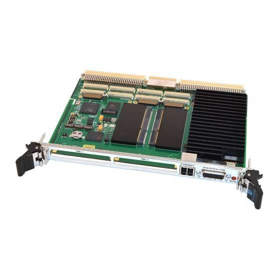
USER’S MANUAL XVME-6500 3.0 HARDWARE INFORMATION AND CONFIGURATION Fig. 3.1.a: XVME-6500 Top View Acromag, Inc. Tel: 248-295-0310 - 15 - - 15 - www.acromag.com http://www.acromag.com... -
Page 17: Module Hardware Switch Configuration
Regulator On SW1-1 is used to configure whether the front panel reset switch can be used to reset the XVME-6500 (and subsequently the whole VME chassis depending on SW4-6). SW1-2 is used to isolate ORB GND (the front panel's chassis connection) from digital ground, if necessary to isolate ground loops. -
Page 18: Core Configuration Switch Sw2
SW2-3 and 2-4 are used to override the automatic VGA monitor detection on the VGA ports. If a monitor connected to a port is not automatically recognized, setting the switches as shown will force a particular VGA port to be active. Acromag, Inc. Tel: 248-295-0310 - 17 - - 17 - www.acromag.com... -
Page 19: Vme Configuration Switch Sw4
If SW4-3 is on, a VME SYSRESETn assertion on the backplane will cause a local reset. Otherwise, the signal will be isolated from the backplane. If a VME64x backplane is being used, SW4-4 can be used to enable Auto Slot Identification. Acromag, Inc. Tel: 248-295-0310 - 18 - - 18 - www.acromag.com... -
Page 20: Jtag Vref Configuration Switch Sw5
Upper Site VREF = 3.3V (J9) JTAG VREF Upper Site VREF = 2.5V Configuration SW5 is used to select the VREF voltage for the XMC/PMC JTAG connections on J8 and J9. Acromag, Inc. Tel: 248-295-0310 - 19 - - 19 - www.acromag.com http://www.acromag.com... -
Page 21: Vme Pcie Configuration Switch Sw6
SW6 is for the PCIe memory configuration of the VME bridge. Do not use a prefetchable memory BAR size greater than 1024 Mbytes while in A32 addressing mode (SW6-1 off). Acromag, Inc. Tel: 248-295-0310 - 20 - - 20 - www.acromag.com... -
Page 22: Vme Configuration Switch Sw7
3.2 Power Supply and Management 3.2.1 Power Options The XVME-6500 can be used in any of the following VMEbus systems, with the associated caveats: • 3-row, 5V-only legacy system. This system will limit the P2 I/O and the incoming power to the XVME-6500 to 60W. -
Page 23: Programmable Cpu Power Limits
USER’S MANUAL XVME-6500 3.2.2 Programmable CPU Power Limits The XVME-6500 features programmable power limits, allowing the user to 'dial-down' the maximum power consumption of the CPU in systems where power is a concern. The graph below shows that the i7-4700EQ CPU... -
Page 24: Power Management
Wake‐up is not possible in this state. Note that S3 (Standby or Sleep), S4 (Hibernate) and S5 (Soft Off) are not supported by the XVME-6500, even if the VME system supports a standby power supply. 3.2.3.2 ACPI Processor States... -
Page 25: Cpu
3.3 CPU ® The Intel Gen 4 (Haswell) CPU available on the XVME-6500 is a 2.4GHz quad- core i7. This 64-bit, 22-nanometer CPU with integrated GT2 graphics contains direct interfaces for DDR3L, DDI, and PCIe x16. In addition, the Direct Media Interface (DMI) is used to connect to the QM87 Platform Control Hub (PCH). -
Page 26: Platform Controller Hub (Pch)
HDA Audio – The HDA audio port is connected to an ALC892 high definition audio codec. Analog stereo line-in and line-out ports are available on the VME P2 connector. Acromag, Inc. Tel: 248-295-0310 - 25 - - 25 - www.acromag.com... -
Page 27: System Memory
1 GB, 2 GB, 4 GB, and 8 GB DDR3 SDRAM densities • 72-bit wide channels (64-bits plus 8 bits of ECC) 3.6 Video 3.6.1 VGA The XVME-6500 uses the Intel® Lynx Point controller to support the analog VGA interface. The VGA interface features include: • Integrated 180 Mhz 24‐bit RAMDAC •... -
Page 28: Dvi
3.6.2.3 Integrated Audio (The information below is from Intel® document No. 328901, “Mobile 4th Generation Intel® Core™ Processor Family Datasheet – Volume 1 of 2”, Rev: 002; September, 2013.) Acromag, Inc. Tel: 248-295-0310 - 27 - - 27 - www.acromag.com... -
Page 29: Configuring The Primary Display
3.7 Intel High Definition Audio ® The XVME-6500 uses Intel High Definition Audio thru an ALC892 Audio CODEC to provide both stereo line-in and stereo line-out connections. Enabling and configuring the HDA is discussed in The APTIO Haswell Core BIOS Manual For Acromag Products. -
Page 30: General I/O
(POST) codes to the dual 7-segment display. For further information regarding the system BIOS and LPC interfaces, refer to The APTIO Haswell Core BIOS Manual For Acromag Products. 3.9.3 Serial Ports Four 16550‐compatible serial ports are supplied by the NCT6776 Super I/O chip: •... -
Page 31: Usb
Link and Activity LEDs are available for each port. • Two ports are available on the front panel's RJ Point 5 connector. One adapter cable is included with the XVME-6500 to connect from the front panel's RJ Point 5 connector to a standard RJ45 connector. •... -
Page 32: Battery Powered Real Time Clock (Rtc)
3.12 Security 3.12.1 Trusted Platform Support The XVME-6500 uses the Atmel AT97SC3204 fully integrated security module, which implements version 1.2 of the Trusted Computing Group (TCG) specification for Trusted Platform Modules (TPM). The TPM includes a cryptographic accelerator capable of computing a 2048-bit RSA signature in 200ms and a 1024-bit RSA signature in 40ms. -
Page 33: System Management
The Intel® HT Technology is enabled by default; no action by the operator is required. For further information on disabling support for this technology, refer to The APTIO Haswell Core BIOS Manual For Acromag Products. 3.13.2 Enhanced Intel SpeedStep Technology (EIST) ®... -
Page 34: Intel ® Trusted Execution Technology (Txt)
TXT works in conjunction with the TPM so that the system software may make trust decisions. The Intel TXT feature is enabled by default. For further information on disabling support for this technology, refer to The APTIO Haswell Core BIOS Manual For Acromag Products. 3.13.5 Intel Turbo Boost Technology ®... -
Page 35: Intel ® Active Management Technology
USER’S MANUAL XVME-6500 Refer to The APTIO Haswell Core BIOS Manual For Acromag Products and the appropriate processor Turbo Implementation Guide for more information. 3.13.6 Intel Active Management Technology ® ® (Note: The following information is from Intel publication “External Design ®... -
Page 36: Thermal Monitoring
APTIO Haswell Core BIOS Manual For Acromag Products. 3.14.4 Thermal Management Hardware The XVME-6500 is available in air-cooled and extended air-cooled models only. A larger double-slot heatsink is also available as an accessory. Please consult the factory for more information. -
Page 37: Watchdog
The Lower Site accepts either PMC or XMC modules, with the module's P4 user I/O routed as 100ohm differential pairs to the optional P0 connector on the XVME-6500. A build option is available to instead route the I/O from the module's P6 connector to the XVME-6500's P0 connector. Please consult factory regarding this option. -
Page 38: Pmc Modules
3.16.2 PMC Modules PMC modules can be used in either or both Upper and Lower Expansion Sites on the XVME-6500, however if one PMC module is used in conjunction with one XMC module the PMC module must be in the Upper Site. -
Page 39: Xbrd-9060 I/O Expander Module
3.16.4 XBRD-9060 I/O Expander Module The optional XBRD-9060 module may be installed in the Upper Site of an air- cooled XVME-6500 to bring more I/O to the front panel, as well as allow mSATA SSD modules to be added for storage. - Page 40 XVME-6500 Example 2: An XVME-6500 is used in a 3-row backplane with 5V only power. The expected expansion card power is 40W. To determine the value to use for PL1: PL1= 57.5W - 40W – 23.5W = -6.0W. The expected expansion card power is too large for this scenario.
-
Page 41: Vme Interface
VME Bridge that is fully compliant with all VME64x data transactions (SBT, BLT, MBLT, 2eVME, and 2eSST) on all common addressing space modes (A16, A24 and A32). This allows the XVME-6500 to take advantage of the higher performance VME protocols, but sill co-exist with VME boards utilizing legacy protocols. -
Page 42: Front Panel Layout
RESET Switch: The front panel switch can be configured to cause a local reset and also may reset the VME backplane, depending on the configuration of SW1-1 and SW4-6. Acromag, Inc. Tel: 248-295-0310 - 41 - - 41 - www.acromag.com http://www.acromag.com... -
Page 43: Firmware/Bios Information And Configuration
XVME-6500. For other, more generic BIOS setup information, refer to The APTIO Haswell Core BIOS Manual For Acromag Products. To access the XVME-6500 specific items in the BIOS setup, select the Acromag menu item. Fig. 4.1.a: Acromag BIOS Setup Menu •... -
Page 44: Service And Repair
5.3 Where to Get Help If the problem persists, the next step should be to visit the Acromag worldwide web site at http://www.acromag.com. Our web site contains the most up-to-date product and software information. -
Page 45: Specifications
USER’S MANUAL XVME-6500 6.0 SPECIFICATIONS 6.1 Physical The XVME-6500 conforms to the 6U Eurocard form-factor. Height 233.35 mm (9.187 in) Depth 160.0 mm (6.3 in) Minimum Backplane Pitch 20.32 mm (0.8 in) Unit Weight with P0 connector: 17.8 oz (0.507 kg) without P0 connector: 17.4 oz (0.494 kg) -
Page 46: Vme Interface
LWR_IO23_P LWR_IO23_N LWR_IO24_N LWR_IO26_N LWR_IO26_P LWR_IO27_N LWR_IO27_P LWR_IO30_N LWR_IO30_P LWR_IO28_N LWR_IO28_P NC = NO CONNECT ENET1 signals may instead be switched to XBRD-9060 I/O Expander module, if installed. Acromag, Inc. Tel: 248-295-0310 - 45 - - 45 - www.acromag.com http://www.acromag.com... -
Page 47: P1 Vme Connector
+3.3V IRQ4# IRQ3# +3.3V IRQ2# IRQ1# +3.3V -12V +12V NC = NO CONNECT The XVME-6500 will use +3.3V from the backplane, if present, but it is not required. Acromag, Inc. Tel: 248-295-0310 - 46 - - 46 - www.acromag.com http://www.acromag.com... -
Page 48: P2 Vme Connector (Standard I/O)
UPR_IO22_N UPR_IO14_P UPR_IO7_P UPR_IO30_P VME_D30 UPR_IO22_P UPR_IO14_N UPR_IO30_N VME_D31 UPR_IO15_N UPR_IO15_P UPR_IO7_N UPR_IO31_P UPR_IO23_P UPR_IO31_N UPR_IO23_N TX- and RX- only used when serial port is in RS-422/RS-485 mode Acromag, Inc. Tel: 248-295-0310 - 47 - - 47 - www.acromag.com http://www.acromag.com... -
Page 49: P2 Vme Connector (Xvme-6300 Compatible I/O - Consult Factory For This Option)
A factory build option makes the P2 I/O compatible with the XVME-6300 pinout, although some PMC I/O signal differences remain from those on the XVME-6300. The highlighted pins below show the pin differences from the standard XVME-6500 I/O. ROW/PIN COM4_TX... -
Page 50: Lower Pmc/Xmc Site
IRDY# DEVSEL# PCIXCAP PU to 3.3V +3.3V AD(15) AD(12) AD(11) AD(9) C/BE(0)# AD(6) AD(5) AD(4) +3.3V AD(3) AD(2) AD(1) AD(0) REQ64# NC = NO CONNECT PU = PULLUP Acromag, Inc. Tel: 248-295-0310 - 49 - - 49 - www.acromag.com http://www.acromag.com... -
Page 51: J12 Lower Pmc Site Pci-X Connector
AD(20) AD(18) AD(16) C/BE(2)# TRDY# +3.3V STOP# PERR# +3.3V SERR# C/BE(1)# AD(14) AD(13) M66EN AD(10) AD(8) +3.3V AD(7) +3.3V ACK64# +3.3V NC = NO CONNECT PU = PULLUP Acromag, Inc. Tel: 248-295-0310 - 50 - - 50 - www.acromag.com http://www.acromag.com... -
Page 52: J13 Lower Pmc Site Pci-X Connector
AD(53) AD(52) AD(51) AD(50) AD(49) AD(48) AD(47) AD(46) AD(45) +3.3V AD(44) AD(43) AD(42) AD(41) AD(40) AD(39) AD(38) AD(37) AD(36) AD(35) AD(34) AD(33) +3.3V AD(32) NC = NO CONNECT Acromag, Inc. Tel: 248-295-0310 - 51 - - 51 - www.acromag.com http://www.acromag.com... -
Page 53: J14 Lower Pmc Site Rear-I/O Connector
LWR_IO18_P LWR_IO19_P LWR_IO18_N LWR_IO19_N LWR_IO20_P LWR_IO21_P LWR_IO20_N LWR_IO21_N LWR_IO22_P LWR_IO23_P LWR_IO22_N LWR_IO23_N LWR_IO24_P LWR_IO25_P LWR_IO24_N LWR_IO25_N LWR_IO26_P LWR_IO27_P LWR_IO26_N LWR_IO27_N LWR_IO28_P LWR_IO29_P LWR_IO28_N LWR_IO29_N LWR_IO30_P LWR_IO31_P LWR_IO30_N LWR_IO31_N Acromag, Inc. Tel: 248-295-0310 - 52 - - 52 - www.acromag.com http://www.acromag.com... -
Page 54: J15 Lower Xmc Site Pcie Connector
This 6-pin Molex 78171-5006 connector carries the Lower PMC or XMC module's JTAG interface. The VREF voltage can be selected between 2.5V, or 3.3V with SW5. SIGNAL JTAG_TDI JTAG_TDO JTAG_TCK JTAG_TMS JTAG_VREF Acromag, Inc. Tel: 248-295-0310 - 53 - - 53 - www.acromag.com http://www.acromag.com... -
Page 55: J16 Lower Xmc Site Rear I/O Connector
This standard 114-pin Samtec ASP-103612-04 connector can, with a build option bring the Lower XMC module's P6 I/O to the XVME-6500's P0 connector instead of the XMC/PMC module's P4 connector. The signals are routed as 100ohm differential pairs. Consult Factory for this option. -
Page 56: Upper Pmc/Xmc Site
IRDY# DEVSEL# PCIXCAP PU to 3.3V +3.3V AD(15) AD(12) AD(11) AD(9) C/BE(0)# AD(6) AD(5) AD(4) +3.3V AD(3) AD(2) AD(1) AD(0) REQ64# NC = NO CONNECT PU = PULLUP Acromag, Inc. Tel: 248-295-0310 - 55 - - 55 - www.acromag.com http://www.acromag.com... -
Page 57: J22 Upper Pmc Site Pci-X Connector
AD(20) AD(18) AD(16) C/BE(2)# TRDY# +3.3V STOP# PERR# +3.3V SERR# C/BE(1)# AD(14) AD(13) M66EN AD(10) AD(8) +3.3V AD(7) +3.3V ACK64# +3.3V NC = NO CONNECT PU = PULLUP Acromag, Inc. Tel: 248-295-0310 - 56 - - 56 - www.acromag.com http://www.acromag.com... -
Page 58: J23 Upper Pmc Site Pci-X Connector
AD(53) AD(52) AD(51) AD(50) AD(49) AD(48) AD(47) AD(46) AD(45) +3.3V AD(44) AD(43) AD(42) AD(41) AD(40) AD(39) AD(38) AD(37) AD(36) AD(35) AD(34) AD(33) +3.3V AD(32) NC = NO CONNECT Acromag, Inc. Tel: 248-295-0310 - 57 - - 57 - www.acromag.com http://www.acromag.com... -
Page 59: J24 Upper Pmc Site Rear I/O Connector
UPR_IO18_P UPR_IO19_P UPR_IO18_N UPR_IO19_N UPR_IO20_P UPR_IO21_P UPR_IO20_N UPR_IO21_N UPR_IO22_P UPR_IO23_P UPR_IO22_N UPR_IO23_N UPR_IO24_P UPR_IO25_P UPR_IO24_N UPR_IO25_N UPR_IO26_P UPR_IO27_P UPR_IO26_N UPR_IO27_N UPR_IO28_P UPR_IO29_P UPR_IO28_N UPR_IO29_N UPR_IO30_P UPR_IO31_P UPR_IO30_N UPR_IO31_N Acromag, Inc. Tel: 248-295-0310 - 58 - - 58 - www.acromag.com http://www.acromag.com... -
Page 60: J25 Upper Xmc Site Pcie Connector
This 6-pin Molex 78171-5006 connector carries the Lower PMC or XMC module's JTAG interface. The VREF voltage can be selected between 2.5V, or 3.3V with SW5. SIGNAL JTAG_TDI JTAG_TDO JTAG_TCK JTAG_TMS JTAG_VREF Acromag, Inc. Tel: 248-295-0310 - 59 - - 59 - www.acromag.com http://www.acromag.com... -
Page 61: J7 Upper Pmc/Xmc Site Expansion Connector
+3.3V +3.3V +1.5V NC = NO CONNECT ENET1 signals may instead be switched to XBRD-9060 I/O Expander module, if installed. ENET1_SEL# Auto-switches ENET1 signals to XBRD-9060 when low. Acromag, Inc. Tel: 248-295-0310 - 60 - - 60 - www.acromag.com http://www.acromag.com... -
Page 62: Front Panel Connectors
Note: The DB-9 serial connector on this dongle cable is wired as a DTE port. SIGNAL USB0_P USB0_N +5V USB POWER VGA_I2C_DAT VGA_RED VGA_GRN VGA_BLUE USB1_P USB1_N +5V VGA POWER VGA_I2C_CLK GND_RED GND_GREEN GND_BLUE COM1_CTS# COM1_RTS# COM1_DSR# COM1_DTR# COM1_TXD COM1_RXD VGA_VSYNC VGA_HSYNC Acromag, Inc. Tel: 248-295-0310 - 61 - - 61 - www.acromag.com http://www.acromag.com... -
Page 63: J4 Dual Ethernet Rj Point 5 Connector
6.2.8 P3 CPU Fan Connector This 5-pin connector, Molex 53398-0571, can be used to power a 5V fan in situations where more cooling is necessary. SIGNAL NO CONNECT FAN TACH FAN PWM Acromag, Inc. Tel: 248-295-0310 - 62 - - 62 - www.acromag.com http://www.acromag.com... -
Page 64: P2 I/O Signal Requirements
It is strongly suggested that ESD protection be included in interface circuitry on the VGA and USB ports. Failure to do so may cause damage the XVME- 6500 in the event of an ESD discharge into the I/O pins. Acromag, Inc. Tel: 248-295-0310 - 63 - - 63 - www.acromag.com... -
Page 65: Power Requirements
USER’S MANUAL XVME-6500 6.4 Power Requirements The power required to properly operate the XVME-6500 module will vary depending on many variables, including the operating system, application software, and the components that the module is integrated with. See notes below for defined variables used to measure the following power values: VDC (+5/-3%) when the backplane supplies +3.3V... -
Page 66: Environmental Considerations
For systems that need maximum performance at higher ambient temperatures and can handle the XVME-6500 consuming an extra slot, a larger heatsink is available as an accessory. Consult factory for more information. -
Page 67: Reliability Prediction
MTBF (Mean Time Between Failure): MTBF in hours using MIL-HDBK-217F, FN2. Per MIL-HDBK-217, Ground Benign, Controlled, G Temperature MTBF (Hours) MTBF (Years) Failure Rate (FIT 25°C 40°C FIT is Failures in 10 hours. Acromag, Inc. Tel: 248-295-0310 - 66 - - 66 - www.acromag.com http://www.acromag.com... -
Page 68: Xvme-6500 Certificate Of Volatility
USER’S MANUAL XVME-6500 6.7 XVME-6500 Certificate of Volatility Certificate of Volatility Acromag Model Manufacturer: XVME-64XX-XXXXX-XX Acromag, Inc. 30765 Wixom Rd Wixom, MI 48393 Volatile Memory Does this product contain Volatile memory (i.e. Memory of whose contents are lost when power is removed) ■... -
Page 69: Xbrd-9060 I/O Expander Accessory Module
7.0 XBRD-9060 I/O Expander Accessory Module The optional XBRD-9060 module may be installed in the Upper Site of an air- cooled XVME-6500 to bring more I/O to the front panel, as well as allow mSATA SSD modules to be added for storage. -
Page 70: Hardware Information And Configuration
(26.8mm) mSATA modules please consult factory. 7. 4 Installation onto XVME-6500 The XBRD-9060 is installed onto the XVME-6500 in the same fashion as a PMC/XMC module. First insert the XBRD-9060 through the front panel at an angle, and then bring the back of the module down to seat into the expansion connector. -
Page 71: Specifications
7.5.1 Physical The XBRD-9060 dimensions are shown below: Length 128.0 mm (5.039 in) Width 74..0 mm (2.913 in) Height from XVME-6500 (includes PCB) 12.6 mm (0.496 in) Unit Weight 2.3 oz (0.067 kg) Acromag, Inc. Tel: 248-295-0310 - 70 - - 70 - www.acromag.com... -
Page 72: Connector Information
USER’S MANUAL XVME-6500 7.5.2 Connector Information 7.5.2.1 J3 Expansion Connector This 60-pin Samtec QTH-030-03-L-D-A-K connector is used for I/O connection to the XVME-6500 CPU module. SIGNAL SIGNAL ENET1_MDI2_N ENET1_MDI0_N ENET1_MDI2_P ENET1_MDI0_P ENET1_MDI3_N ENET1_MDI1_N ENET1_MDI3_P ENET1_MDI1_P SATA1_TX_N SATA0_TX_N SATA1_TX_P SATA0_TX_P SATA1_RX_N... -
Page 73: J7 Ethernet Connector
SIGNAL COM3_RXD COM3_TXD 7.5.2.4 RS-232 Serial Adapter Cable Use the included shielded adapter cable to have a standard DB-9 connector wired as a DTE port. SIGNAL COM3_TXD COM3_RXD Acromag, Inc. Tel: 248-295-0310 - 72 - - 72 - www.acromag.com http://www.acromag.com... -
Page 74: J4 Usb 2.0 Connector
Note: Even though the connector is a USB 3.0 connector, it will only function at USB 2.0 or lower speeds. There is no USB 3.0 superspeed signal connection. SIGNAL +5V USB POWER USB3_N USB3_P Acromag, Inc. Tel: 248-295-0310 - 73 - - 73 - www.acromag.com http://www.acromag.com... -
Page 75: J1 Msata Connector
XBRD-9060. SIGNAL SIGNAL +3.3V +1.5V PLT_RST# SATA0_RX_N +3.3V SATA0_RX_P +1.5V SMB_CLK SATA0_TX_N SMB_DATA SATA0_TX_P +3.3V +3.3V +1.5V +3.3V NC = NO CONNECT Acromag, Inc. Tel: 248-295-0310 - 74 - - 74 - www.acromag.com http://www.acromag.com... -
Page 76: J6 Msata Connector
XBRD-9060. SIGNAL SIGNAL +3.3V +1.5V PLT_RST# SATA1_RX_N +3.3V SATA1_RX_P +1.5V SMB_CLK SATA1_TX_N SMB_DATA SATA1_TX_P +3.3V +3.3V +1.5V +3.3V NC = NO CONNECT Acromag, Inc. Tel: 248-295-0310 - 75 - - 75 - www.acromag.com http://www.acromag.com... -
Page 77: Power Requirements
The power used by the XBRD-9060 board without any mSATA modules installed is negligible. mSATA power draws from the available +3.3V on the XVME-6500. +1.5V is also available, but usage of this voltage on mSATA modules is not widespread. 7.7 Environmental Considerations Operating Temperature: -40°C to 75°C... -
Page 78: Xbrd-9060 Certificate Of Volatility
Storage of User Data Refer to mSATA module module □ No documentation dependent Acromag Representative Name: Title: Email: Office Phone: Office Fax: Joseph Primeau Dir. of Sales solutions@acromag.com 248-295-0310 248-624-9234 Marketing Acromag, Inc. Tel: 248-295-0310 - 77 - - 77 - www.acromag.com http://www.acromag.com... -
Page 79: Xvme-9640 Rear-Transition Accessory Module
8.0 XVME-9640 Rear-Transition Accessory Module The optional XVME-9640 module may be installed into the rear slot directly behind the XVME-6500 to easily access all of the available I/O on the XVME-6500's P2, and optionally P0 connectors, as well as allow mSATA SSD modules to be added for storage. -
Page 80: Ordering Information
In a high-vibration environment the addition of a removable thread locker, such as Loctite 242, is recommended. For installation of half-size (26.8mm) mSATA modules please consult factory. Acromag, Inc. Tel: 248-295-0310 - 79 - - 79 - www.acromag.com... -
Page 81: Specifications
8.4.2 Connector Information 8.4.2.1 RJ0 VME Connector (Optional) This optional connector is a standard 6-row, 2mm Type B, 95-pin Harting 17-25-095-2102. It contains 2 Ethernet and the Lower Site's PMC I/O (XMC instead with XVME-6500 build option) ROW/PIN ENET0_MX0_P ENET0_MX0_N... -
Page 82: Rj2 Vme Connector
UPR_IO7_P UPR_IO30_P UPR_IO22_P UPR_IO14_N UPR_IO30_N UPR_IO15_N UPR_IO15_P UPR_IO7_N UPR_IO31_P UPR_IO23_P UPR_IO31_N UPR_IO23_N NC = NO CONNECT TX- and RX- only used when serial port is in RS-422/RS-485 mode Acromag, Inc. Tel: 248-295-0310 - 81 - - 81 - www.acromag.com http://www.acromag.com... -
Page 83: J1 Vga Connector
This 4-pin USB 2.0 A-style, Molex 67329-8001, connector Brings USB port 5 out the front panel. The power is current limited to 1A (shared with J4). SIGNAL +5V USB POWER USB5_N USB5_P Acromag, Inc. Tel: 248-295-0310 - 82 - - 82 - www.acromag.com http://www.acromag.com... -
Page 84: J7 Dvi-D Connector
VGA connector. SIGNAL DVI_P2_N DVI_P2_P DVI_I2C_CLK DVI_I2C_DAT DVI_P1_N DVI_P1_P +5V DVI (1A MAX) HOT PLUG DETECT DVI_P0_N DVI_P0_P DVI_CLK_P DVI_CLK_N NC = NO CONNECT Acromag, Inc. Tel: 248-295-0310 - 83 - - 83 - www.acromag.com http://www.acromag.com... -
Page 85: J8 Dual Ethernet Rj Point 5 Connector
SIGNAL ENET0_MX0_P ENET0_MX0_N ENET0_MX1_P ENET0_MX1_N ENET0_MX2_P ENET0_MX2_N ENET0_MX3_P ENET0_MX3_N ENET1_MX0_P ENET1_MX0_N ENET1_MX1_P ENET1_MX1_N ENET1_MX2_P ENET1_MX2_N ENET1_MX3_P ENET1_MX3_N ENET1 signals not available when enabled on XBRD-9060 I/O Expander module. Acromag, Inc. Tel: 248-295-0310 - 84 - - 84 - www.acromag.com http://www.acromag.com... -
Page 86: J5 Upper Pmc/Xmc User I/O Connector
USER’S MANUAL XVME-6500 8.4.2.8 J5 Upper PMC/XMC User I/O Connector This 68-pin SCSI-3 style, TE 5787082-7, connector carries the PMC/XMC module rear I/O from the Upper PMC/XMC site on the XVME-6500. SIGNAL SIGNAL UPR_IO0_P UPR_IO0_N UPR_IO1_P UPR_IO1_N UPR_IO2_P UPR_IO2_N UPR_IO3_P... -
Page 87: P4 Lower Pmc/Xmc User I/O Connector (Optional)
USER’S MANUAL XVME-6500 8.4.2.9 P4 Lower PMC/XMC User I/O Connector (Optional) This optional 40-pin connector, Samtec QTH-020-01-F-D-DP-A-K, carries the PMC/XMC module rear I/O from the Lower PMC/XMC site on the XVME-6500. SIGNAL SIGNAL UPR_IO0_P UPR_IO10_P UPR_IO0_N UPR_IO10_N UPR_IO1_P UPR_IO11_P UPR_IO1_N... -
Page 88: P3 Lower Pmc/Xmc User I/O Connector (Optional)
USER’S MANUAL XVME-6500 8.4.2.11 P3 Lower PMC/XMC User I/O Connector (Optional) This optional 40-pin connector, Samtec QTH-020-01-F-D-DP-A-K, carries the PMC/XMC module rear I/O from the Lower PMC/XMC site on the XVME-6500. SIGNAL SIGNAL UPR_IO4_P UPR_IO14_P UPR_IO4_N UPR_IO14_N UPR_IO5_P UPR_IO15_P UPR_IO5_N... -
Page 89: J6 Msata Connector
This standard 52-pin mSATA connector, TE 2041119-1, is used for connecting an mSATA drive module to the XBRD-9060. SIGNAL SIGNAL +3.3V SATA2_RX_N +3.3V SATA2_RX_P SATA2_TX_N SATA2_TX_P +3.3V +3.3V +3.3V NC = NO CONNECT Acromag, Inc. Tel: 248-295-0310 - 88 - - 88 - www.acromag.com http://www.acromag.com... -
Page 90: J2 Msata Connector
This standard 52-pin mSATA connector, TE 2041119-1, is used for connecting an mSATA drive module to the XBRD-9060. SIGNAL SIGNAL +3.3V SATA3_RX_N +3.3V SATA3_RX_P SATA3_TX_N SATA3_TX_P +3.3V +3.3V +3.3V NC = NO CONNECT Acromag, Inc. Tel: 248-295-0310 - 89 - - 89 - www.acromag.com http://www.acromag.com... -
Page 91: Power Requirements
The power used by the XVME-9640 board without any mSATA modules installed is negligible. mSATA power draws from the available +3.3V on the XVME-6500. Note: +1.5V is NOT available, but usage of this voltage on mSATA modules is not widespread. -
Page 92: Xvme-9640 Certificate Of Volatility
Storage of User Data Refer to mSATA module module □ No documentation dependent Acromag Representative Name: Title: Email: Office Phone: Office Fax: Joseph Primeau Dir. of Sales solutions@acromag.com 248-295-0310 248-624-9234 Marketing Acromag, Inc. Tel: 248-295-0310 - 91 - - 91 - www.acromag.com http://www.acromag.com... -
Page 93: Revision History
Changed default SSD write protect settings from hardware to software. 27 JAN 2017 BLD/DAG/ARP Changed the name of the referenced BIOS manual to The APTIO Haswell Core BIOS Manual For Acromag Products. Updated Environmental Considerations sections. Updated P1 Audio Connector information. 23 MAY 2017 ENZ/MJO Updated information on SW4 and reset behavior.
Need help?
Do you have a question about the XVME-6500 and is the answer not in the manual?
Questions and answers