Table of Contents
Advertisement
Quick Links
Advertisement
Table of Contents

Related Manuals for Acromag AXM-A75


Summary of Contents for Acromag AXM-A75
- Page 1 Artisan Technology Group is your source for quality new and certified-used/pre-owned equipment SERVICE CENTER REPAIRS WE BUY USED EQUIPMENT • FAST SHIPPING AND DELIVERY Experienced engineers and technicians on staff Sell your excess, underutilized, and idle used equipment at our full-service, in-house repair center We also offer credit for buy-backs and trade-ins •...
- Page 2 AXM-A75 Multifunction I/O Mezzanine Module USER’S MANUAL ACROMAG INCORPORATED 30765 South Wixom Road Wixom, MI 48393-2417 U.S.A. Tel: (248)295-0310 Email: solutions@acromag.com Copyright 2013, Acromag, Inc., Printed in the USA. Data and specifications are subject to change without notice. 8500927G...
-
Page 3: Table Of Contents
Analog Inputs: Noise and Grounding Considerations ..............9 Non-Isolation Considerations ......................9 PROGRAMMING INFORMATION ...................... 9 AXM-A75 Memory Map ........................9 FLASH Data Format ........................13 Board Status and Reset Register (Read/Write, PCIBar2 + 8000H) ..........14 Control Register - (Read/Write, PCIBar2 + 8100H) ................ 15 Status Register 0 - (Read/Write, PCIBar2 + 8104H) ............... - Page 4 AXM-A75 User’s Manual Multifunction I/O Mezzanine Board _____________________________________________________________________________________ Digital I/O ............................23 Analog Outputs ..........................24 Analog Inputs ..........................24 SERVICE AND REPAIR ........................25 SERVICE AND REPAIR ASSISTANCE ....................25 PRELIMINARY SERVICE PROCEDURE ....................25 WHERE TO GET HELP ........................25 SPECIFICATIONS ..........................
- Page 5 Multifunction I/O Mezzanine Board _____________________________________________________________________________________ The information contained in this manual is subject to change without notice. Acromag, Inc. makes no warranty of any kind with regard to this material, including, but not limited to, the implied warranties of merchantability and fitness for a particular purpose. Further, Acromag, Inc. assumes no responsibility for any errors that may appear in this manual and makes no commitment to update, or keep current, the information contained in this manual.
-
Page 6: General Information
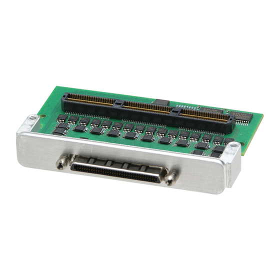
Multifunction I/O Mezzanine Board _____________________________________________________________________________________ GENERAL INFORMATION The AXM-A75 is a high speed analog input/output mezzanine board compatible with Acromag’s line of re-configurable PMC and XMC FPGA modules. The AXM-A75 has 16 differential analog inputs, 8 analog outputs and 16 digital inputs/outputs. -
Page 7: Engineering Design Kit
ENGINEERING DESIGN KIT Acromag does not provide an engineering design kit specifically for the AXM-A75 module. However, an example design is included in the Engineering Design Kit of the PMC/XMC base board. Refer to the PMC/XMC base board’s manual for further information on the available Engineering Design Kit. - Page 8 AXM-A75 User’s Manual Multifunction I/O Mezzanine Board _____________________________________________________________________________________ XMC modules, plus the AXM-A75 within the voltage tolerances specified. IMPORTANT: Adequate air circulation must be provided to prevent a temperature rise above the maximum operating temperature. The lack of air circulation within the computer chassis is a cause for some concern.
-
Page 9: Front Panel Field I/O Connector J1
_____________________________________________________________________________________ Front Panel Field I/O Connector J1 The AXM-A75 front panel field I/O connector (J1) is a 68 pin VHDCI receptacle. A cable assembly and termination panel (or user defined terminations) can be quickly mated to the field I/O connector. The pin assignment for this connector is shown in Table 2-1. -
Page 10: Analog Inputs: Noise And Grounding Considerations
The remaining memory space is defined in the base board’s User’s Manual. AXM-A75 Memory Map The AXM-A75 specific memory space address map for the board is shown in Table 3-1. Note that the base address from the base PMC/XMC module in memory space must be added to the addresses shown to properly access the board registers. - Page 11 AXM-A75 User’s Manual Multifunction I/O Mezzanine Board _____________________________________________________________________________________ PCIBar2 + PCIBar2 + (Hex) (Hex) 8107 Status Register 0 8104 810B Status Register 1 8108 810F Digital I/O 810C 8113 Conversion Timer 8110 8117 FLASH 8114 data 811B Digital I/O Direction...
- Page 12 AXM-A75 User’s Manual Multifunction I/O Mezzanine Board _____________________________________________________________________________________ PCIBar2 + PCIBar2 + (Hex) (Hex) 8297 ADC 10 gain correction 8294 829B ADC 10 offset 8298 829F unused 829C 82A3 ADC 11 data 82A0 82A7 ADC 11 gain correction 82A4 82AB...
- Page 13 AXM-A75 User’s Manual Multifunction I/O Mezzanine Board _____________________________________________________________________________________ PCIBar2 + PCIBar2 + (Hex) (Hex) DAC 3 fine 832B gain 8328 DAC 3 832F offset 832C 8333 DAC 4 data 8330 DAC 4 coarse 8337 gain 8334 DAC 4 fine 833B...
-
Page 14: Flash Data Format
FLASH contents. All numeric constants are 32 bit values stored in little endian byte order. Table 3-2 FLASH Memory Map Addr Addr 0007 FLASH ID = “AXM-A75” (null terminated 0000 character string) 000B 10.24 Volt Range Channel 1 Offset 0008 000F 10.24 Volt Range Channel 2 Offset... -
Page 15: Board Status And Reset Register (Read/Write, Pcibar2 + 8000H)
Writing a “1” to bit 31 of this register will cause a software reset affecting both the PMC base board and the majority of AXM-A75 registers. Bits 15 to 13 are used for AXM identification code. -
Page 16: Control Register - (Read/Write, Pcibar2 + 8100H)
AXM-A75 User’s Manual Multifunction I/O Mezzanine Board _____________________________________________________________________________________ FUNCTION 30- 16 Reserved for base board AXM Identification bits (Read Only) 15 - 13 AXM-EDK “001” AXM-A75 “011” 12 - 2 Reserved for base board FIFO overflow interrupt pending FIFO half full interrupt pending... -
Page 17: Status Register 0 - (Read/Write, Pcibar2 + 8104H)
AXM-A75 User’s Manual Multifunction I/O Mezzanine Board _____________________________________________________________________________________ Status Register 0 - (Read/Write, PCIBar2 + 8104H) Status Register 0 provides access to the FIFO overflow and half full status bits for each channel. Table 3-5 Status Register 0 8104H FUNCTION 31- 16 FIFO overflow interrupt pending / clear channel [16 .. -
Page 18: Flash Data Register - (Read/Write, Pcibar2 + 8114H)
ADC values to the FIFOs. Typical start-up operation would include reading factory calibration constants from AXM-A75 on-board FLASH memory and writing the appropriate correction values for the currently - 17 -... -
Page 19: Adc Data Format
AXM-A75 User’s Manual Multifunction I/O Mezzanine Board _____________________________________________________________________________________ selected full scale range to the gain and offset registers for each channel. ADC Data Format The output from the ADC is offset binary format as shown in Table 3-12. The full scale range (±10.24, ±5.12, ±2.56, ±1.28) is controlled by the gain selection in the control register. -
Page 20: Uncalibrated Adc Performance
AXM-A75 User’s Manual Multifunction I/O Mezzanine Board _____________________________________________________________________________________ to correct for gain errors. There is a separate gain register for each channel. Table 3-13 Gain Register Number Format Binary Fixed Point 31 - 17 (unused, read as 0) 1/16 1/32... -
Page 21: Dac Channels
DAC values to the outputs. Typical start-up operation would include reading factory calibration constants from AXM-A75 on-board FLASH memory and writing the appropriate correction values for the currently selected full scale range to the coarse gain, fine gain and offset registers for each channel. -
Page 22: Dac Coarse Gain Register
AXM-A75 User’s Manual Multifunction I/O Mezzanine Board _____________________________________________________________________________________ each channel (See Table 3-4). The FSR choices are ±10, ±10.2564 and ±10.5263 Volts. Table 3-14 DAC Data Format Volts DIGITAL OUTPUT +FSR * 32767/32768 FFFF +FSR * 1/32767 8001 Midscale (zero) -
Page 23: Dac Offset Register
THEORY OF OPERATION Field I/O Connections The field I/O interface to the AXM-A75 is provided through connector P1 (refer to Table 2-1). Field I/O signals are NON-ISOLATED. This means that the field return and logic common have a direct electrical connection to each other. -
Page 24: Digital I/O
Digital I/O A block diagram of a single digital I/O channel is shown in Figure 2 Digital I/O. This structure is replicated 16 times on the AXM-A75. The signal DIG_OUT_STROBE is activated upon a write to the Digital I/O register. The level of DIG_IO_n is returned upon a read of the Digital I/O register. -
Page 25: Analog Outputs
AXM-A75 User’s Manual Multifunction I/O Mezzanine Board _____________________________________________________________________________________ driven onto the DIG_IO_n signal. The level translator is a NXP GTL2010. Figure 2 Digital I/O Analog Outputs Two Analog Devices AD5764R quad bipolar voltage output DACs are used to provide the eight analog output channels. Each DAC uses its own on-chip reference as its reference source. -
Page 26: Service And Repair
Surface-Mounted Technology (SMT) boards are generally difficult to repair. It is highly recommended that a non-functioning board be returned to Acromag for repair. The board can be damaged unless special SMT repair and service tools are used. Further, Acromag has automated test equipment that thoroughly checks the performance of each board. -
Page 27: Specifications
Board Thickness ......1.59 mm (0.062 inches) WARNING: The AXM-A75 length dimension exceeds the “CMC I/O envelope” as shown in IEEE 1386- 2001 Figure 4.1 and Figure 4.2 by 7.5mm (limited to 31mm) and is not compatible with all PMC/XMC carriers. -
Page 28: Power Requirements
AXM-A75 User’s Manual Multifunction I/O Mezzanine Board _____________________________________________________________________________________ Power Requirements +3.3 Volts (5%) ......39 mA typical 50 mA maximum +5 Volts (5%) ....... 54 mA typical 65 mA maximum +12V (5%) ........103 mA typical 115 mA maximum -12V (5%)........92 mA typical... -
Page 29: Difference Amplifier
Software calibration eliminates these error components Acromag does not temperature cycle this product before shipping to customers. If the product is operated at the extremes of its temperature range, the voltage reference could drift by the amount specified for first cycle. -
Page 30: Analog Outputs
AXM-A75 User’s Manual Multifunction I/O Mezzanine Board _____________________________________________________________________________________ ANALOG OUTPUTS Digital to Analog Converter Device ..........ADI AD5764RB Resolution ........16 bits Output Ranges ......±10, ±10.2564, and ±10.5263 V Settling Time ......... 8 µS typical full-scale step to ±1 LSB 10 µS maximum... -
Page 31: Appendix
AXM-A75 User’s Manual Multifunction I/O Mezzanine Board _____________________________________________________________________________________ APPENDIX CABLE: MODEL 5028-420 (Ultra SCSI/VHDCI male to SCSI-3 male, Round, Shielded) Type: Round shielded cable, 34-wire pairs (Ultra SCSI/VHDCI male and SCSI-3 male connectors). The cable length is 2 meters (6.56 feet). -
Page 32: Termination Panel: Model 5025-288
Type: Termination Panel for 68 Pin SCSI-3 Cable Connection Application: To connect field I/O signals to the board. Termination Panel: Acromag Part 4001-066. The 5025-288 termination panel facilitates the connection of up to 68 field I/O signals and connects to the board (connectors only) via a round shielded cable (Model 5028-432). -
Page 33: Drawings
AXM-A75 User’s Manual Multifunction I/O Mezzanine Board _____________________________________________________________________________________ DRAWINGS 2 METERS (78.72 INCHES, +4.0 / -0.0 INCHES) TOP VIEW PIN 34 PIN 68 PIN 34 PIN 68 PIN 1 PIN 35 PIN 1 PIN 35 FRONT VIEW MODEL 5028-420 ULTRA SCSI/VHDCI TO... - Page 34 Added support for XMC-7KxxxAX modules. 29-MAY-15 Added support for XMC-7A200. 04-JUNE-15 Added note about IEEE-1386 non-compliance on page 4 and 26. Update Acromag Representative in Certificate of Volatility. 19 FEB 2018 FJM/ARP Update the Certificate of Volatility -- change the flash size from 1M bits to 8M bits.
- Page 35 Artisan Technology Group is your source for quality new and certified-used/pre-owned equipment SERVICE CENTER REPAIRS WE BUY USED EQUIPMENT • FAST SHIPPING AND DELIVERY Experienced engineers and technicians on staff Sell your excess, underutilized, and idle used equipment at our full-service, in-house repair center We also offer credit for buy-backs and trade-ins •...
Need help?
Do you have a question about the AXM-A75 and is the answer not in the manual?
Questions and answers