
Related Manuals for Acromag APMC4110


Summary of Contents for Acromag APMC4110
- Page 1 (217) 352-9330 | Click HERE Find the Acromag / Xembedded / Xycom APMC4110 at our website:...
- Page 2 STANDALONE PCI INTERFACE MODULE USER’S MANUAL ACROMAG INCORPORATED Tel: (248) 295-0310 30765 South Wixom Road Fax: (248) 624-9234 P.O. BOX 437 Wixom, MI 48393-7037 U.S.A. Copyright 2010, Acromag, Inc., Printed in the USA. 8500-899-A10L000 Data and specifications are subject to change without notice.
-
Page 3: Table Of Contents
This is very important where property loss or human life is involved. It is important that you perform satisfactory overall system design and it is agreed between you and Acromag, that this is your responsibility. The information of this manual may change without notice. -
Page 4: General Information
___________________________________________________________________ 1.0 General Information The Acromag APMC4110 Powered PMC Carrier is a board that functions as a stand-alone PCI interface. Using an external power supply, the carrier allows any industry standard PMC module to be mounted without an accompany processor. The user has full access to the field I/O via two 50- pin ribbon cable connectors, P1 and P2. - Page 5 Differential Ch22- (46) Differential Ch23+ (47) Differential Ch23- (48) Table 1.1: Powered PMC Carrier Board Field I/O Pin Connections for P1 Note that the number in parenthesis corresponds to rear I/O PMC P4 pin number. ________________________________________________________________________ Acromag, Inc. Tel:248-624-1541 Fax:248-624-9234 Email:solutions@acromag.com http://www.acromag.com...
- Page 6 Differential Ch31+ (63) Differential Ch31- (64) Table 1.2: Powered PMC Carrier Board Field I/O Pin Connections for P2 Note that the number in parenthesis corresponds to rear I/O PMC P4 pin number. ________________________________________________________________________ Acromag, Inc. Tel: 248-295-0310 Fax:248-624-9234 Email:solutions@acromag.com http://www.acromag.com...
-
Page 7: Power
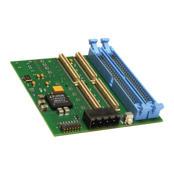
COMMON 1.3 MANUAL RESET The APMC4110 module features a manual reset button. This is a SPST switch which can be pressed to assert the active-low RST# signal and reset the PMC module. A reset delay chip is used on the board to keep RST# asserted for a minimum of 140ms after the +5VDC rail has risen above 1V. - Page 8 APMC4110 User’s Manual Standalone PMC Carrier ___________________________________________________________________ Figure 1.1: APMC4110 Feature Location Power Xilinx JTAG connector connector Manual Reset Button ________________________________________________________________________ Acromag, Inc. Tel: 248-295-0310 Fax:248-624-9234 Email:solutions@acromag.com http://www.acromag.com...
-
Page 9: Preparation For Use
For repairs to a product damaged in shipment, refer to the Acromag Service Policy to obtain return instructions. It is suggested that salvageable shipping cartons and packing material be saved for future use in the event the product must be shipped. -
Page 10: Service And Repair Assistance
CAUTION: POWER MUST BE TURNED OFF BEFORE REMOVING OR INSERTING BOARDS 3.2 WHERE TO GET HELP If you continue to have problems, your next step should be to visit the Acromag worldwide web site at http://www.acromag.com. Our web site contains the most up-to-date product and software information. -
Page 11: Specifications
-12.0 VDC(±10%) 0 mA Note that these power requirements are for the APMC4110 only. The +3.3V is generated on the APMC4110 from 5V via a DC/DC converter. ±12.0 VDC is routed directly to the PMC module and must be provided only if required by the PMC module. - Page 12 ■ No Type Size: User Modifiable Function: Process to Sanitize: (EEPROM, Flash, etc.) □ Yes □ No Type Size: User Modifiable Function: Process to Sanitize: (EEPROM, Flash, etc.) □ Yes □ No ________________________________________________________________________ Acromag, Inc. Tel: 248-295-0310 Fax:248-624-9234 Email:solutions@acromag.com http://www.acromag.com...
Need help?
Do you have a question about the APMC4110 and is the answer not in the manual?
Questions and answers