Table of Contents
Advertisement
Quick Links
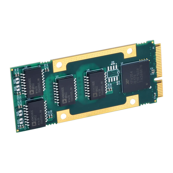
AP512 AcroPack
Isolated RS-485 Serial Communication Module
USER'S MANUAL
ACROMAG INCORPORATED
30765 South Wixom Road
Wixom, MI 48393-2417 U.S.A.
Tel: (248) 295-0310
Email: solutions@acromag.com
Copyright 2016, Acromag, Inc., Printed in the USA.
Data and specifications are subject to change without notice.
8501084D
Advertisement
Table of Contents

Related Manuals for Acromag AcroPack AP512


Summary of Contents for Acromag AcroPack AP512
- Page 1 Isolated RS-485 Serial Communication Module USER’S MANUAL ACROMAG INCORPORATED 30765 South Wixom Road Wixom, MI 48393-2417 U.S.A. Tel: (248) 295-0310 Email: solutions@acromag.com Copyright 2016, Acromag, Inc., Printed in the USA. Data and specifications are subject to change without notice. 8501084D...
-
Page 2: Table Of Contents
Table 2.1 Field I/O Connector Pin Assignments ................10 2.5 RS-422/485 Termination ..................... 13 2.6 Isolation ........................13 2.7 Logic Interface Connector ................... 13 Table 2.2: Logic Interface Connections ..................14 Acromag, Inc. Tel: 248-295-0310 - 1 - - 1 - https://www.acromag.com http://www.acromag.com... - Page 3 4.0 SERVICE AND REPAIR ....................35 4.1 Service and Repair Assistance ..................35 4.2 Preliminary Service Procedure ..................35 4.3 Where to Get Help ...................... 35 5.0 SPECIFICATIONS ......................36 Acromag, Inc. Tel: 248-295-0310 - 2 - - 2 - https://www.acromag.com http://www.acromag.com...
- Page 4 Table 5.4 MTBF (all models) .........................38 5.5 PCIe Bus Specifications ....................38 APPENDIX A .......................... 39 AP-CC-01 Heatsink Kit Installation ..................39 CERTIFICATE OF VOLATILITY ..................42 REVISION HISTORY ......................43 Acromag, Inc. Tel: 248-295-0310 - 3 - - 3 - https://www.acromag.com http://www.acromag.com...
-
Page 5: General Information
The information contained in this manual is subject to change without notice, and Acromag, Inc. (Acromag) does not guarantee its accuracy. Acromag makes no warranty of any kind with regard to this material, including, but not limited to, the implied warranties of merchantability and fitness for a particular purpose. -
Page 6: Acropack Information - All Models
• Internal Isolated Power – Isolated power is created onboard using Analog Devices ADM2882E Full Duplex RS-485 transceivers, so isolated power does not need to be supplied externally. Acromag, Inc. Tel: 248-295-0310 - 5 - - 5 - https://www.acromag.com http://www.acromag.com... -
Page 7: Key Features Pcie Interface
Compatibility – PCI Express Base Specification v2.1 compliant PCI Express Endpoint. 1.4 Signal Interface Products This AcroPack module will mate directly to all Acromag AP carriers. Once connected, the module is accessed via a front panel connector. The cables and termination panels are also available. For optimum performance with the AP512 communication module, use of the shortest possible length of shielded I/O cable is recommended. -
Page 8: Windows
AcroPack modules, VPX I/O board products, and PCIe I/O Cards. The software is implemented as a library of “C” functions which link with existing user code to make possible simple control of all Acromag AcroPack modules. 1.6 References The following resources regarding AcroPack modules are available for download on Acromag’s website or by contacting your sales representative. -
Page 9: Preparation For Use
It is important that the user employ satisfactory overall system design. It is understood and agreed by the Buyer and Acromag that this is the Buyer's responsibility. -
Page 10: Installation Considerations
Refer to the specifications section for loading and power requirements. Be sure that the system power supplies are able to accommodate the power IMPORTANT: Adequate air requirements of the system boards, plus the installed Acromag board, circulation must be provided to within the voltage tolerances specified. - Page 11 RSVD/ISOL RSVD/ISOL RSVD/ISOL Field I/O 12 RXD+_B RSVD/ISOL RSVD/ISOL RSVD/ISOL Field I/O 14 RXD-_B RSVD/ISOL RSVD/ISOL RSVD/ISOL Field I/O 16 TXD-_B RSVD/ISOL RSVD/ISOL RSVD/ISOL Field I/O 18 TXD+_B Acromag, Inc. Tel: 248-295-0310 - 10 - - 10 - https://www.acromag.com http://www.acromag.com...
- Page 12 RSVD/ISOL RSVD/ISOL RSVD/ISOL Field I/O 30 RXD-_C RSVD/ISOL RSVD/ISOL RSVD/ISOL Field I/O 32 TXD-_C RSVD/ISOL RSVD/ISOL RSVD/ISOL Field I/O 34 TXD+_C RSVD/ISOL RSVD/ISOL Field I/O 35 Isolated GND_D Acromag, Inc. Tel: 248-295-0310 - 11 - - 11 - https://www.acromag.com http://www.acromag.com...
- Page 13 RSVD/ISOL RSVD/ISOL Field I/O 41 TXD-_D RSVD/ISOL RSVD/ISOL RSVD/ISOL Field I/O 43 TXD+_D RSVD/ISOL RSVD/ISOL RSVD/ISOL RSVD/ISOL RSVD/ISOL RSVD/ISOL RSVD/ISOL RSVD/ISOL RSVD/ISOL RSVD/ISOL RSVD/ISOL RSVD/ISOL RSVD/ISOL RSVD/ISOL RSVD/ISOL Acromag, Inc. Tel: 248-295-0310 - 12 - - 12 - https://www.acromag.com http://www.acromag.com...
-
Page 14: Rs-422/485 Termination
Threaded metric M2.5 screws and spacers are supplied with the AP carriers to provide additional stability for harsh environments (see carrier documentation for assembly details). Acromag, Inc. Tel: 248-295-0310 - 13 - - 13 - https://www.acromag.com http://www.acromag.com... - Page 15 Note 5: The SM bus signals SMB_CLK and SMB_DATA will be used to clock a carrier location serial stream from the carrier, however this is not supported on the AP512 module. Note 6: TDI is tied to TDO on the AP512 module as it does not use JTAG. Acromag, Inc. Tel: 248-295-0310 - 14 - - 14 - https://www.acromag.com...
-
Page 16: Programming Information
Configuration Address space. This board provides 512 bytes of configuration registers for this purpose. It contains the configuration registers shown in the following table to facilitate Acromag, Inc. Tel: 248-295-0310 - 15 - - 15 - https://www.acromag.com... - Page 17 Only 8K is used, as the upper 8K is for a second 'slave' UART' connected to the master, which does not exist on the AP512 module. Acromag, Inc. Tel: 248-295-0310 - 16 - - 16 - https://www.acromag.com...
-
Page 18: Uart And Device Configuration Registers
0x0087 TIMERMSB Read/WRITE Timer MSB Bits [7:0] = 0x00 Individual UART channels can only control the bit pertaining to that channel in the registers at address offset 0x088-0x08B Acromag, Inc. Tel: 248-295-0310 - 17 - - 17 - https://www.acromag.com http://www.acromag.com... -
Page 19: Uart Channel Configuration Registers
RX and the TX FIFO can be read from/written to, as shown in Table 3.2. The following is an extract from the table showing the memory locations that support 32-bit Acromag, Inc. Tel: 248-295-0310 - 18 - - 18 - https://www.acromag.com... - Page 20 FCTR - Feature Control Register Read/Write 0x1001 EFR - Enhanced Function Read/Write Register 0x1010 TXCNT - Transmit FIFO Level Read-only Counter Write-only TXTRG – Transmit FIFO Trigger Level Acromag, Inc. Tel: 248-295-0310 - 19 - - 19 - https://www.acromag.com http://www.acromag.com...
-
Page 21: Rhr - Receiver Holding Register (Read Only)
(TxD). However, the THR data will not pass to the TxD line unless the transceiver is first enabled. The transceiver must be enabled to transmit data by setting bit-1 of the MCR Acromag, Inc. Tel: 248-295-0310 - 20 - - 20 - https://www.acromag.com... -
Page 22: Dll & Dlm - Divisor Latch Registers, Ports A-H (R/W)
(based on the 14.7456MHz clock). A different external crystal can replace the 14.7456MHz crystal on the circuit board to obtain unique clock rates. You may contact Acromag Applications Engineering to explore Acromag, Inc. Tel: 248-295-0310 - 21 - - 21 - https://www.acromag.com... - Page 23 Table 3.5 Baud Rate BAUD RATE DIVISOR (N) Divisors(14.7456MHZ) Decimal Bit-7=1 Bit-7=0 (HEX) (HEX) 4608 1200 2400 1200 4800 2400 9600 3600 14,400 4800 19,200 7200 28,800 9600 38,400 19,200 76,800 Acromag, Inc. Tel: 248-295-0310 - 22 - - 22 - https://www.acromag.com http://www.acromag.com...
-
Page 24: Ier - Interrupt Enable Register (R/W)
The clock/oscillator circuit is disabled in sleep mode. The UART will not lose the programmed bits when sleep mode is activated or deactivated. The UART will not enter sleep Acromag, Inc. Tel: 248-295-0310 - 23 - - 23 - https://www.acromag.com... -
Page 25: Isr - Interrupt Status Register (Read Only)
Table 3.7 Interrupt source LEVEL Bit5 to Bit0 000110 Receiver Line Status (see LSR bits 1-4) 000100 Received Data Ready or Trigger Level reached. 001100 Receive Data Time Out. Acromag, Inc. Tel: 248-295-0310 - 24 - - 24 - https://www.acromag.com http://www.acromag.com... -
Page 26: Fcr - Fifo Control Register (Write Only)
FIFO interrupt. An interrupt will be issued when the number of characters in the FIFO drops below the selected trigger level. One of four trigger levels can be selected. bit 5 bit 4 Trigger Level Acromag, Inc. Tel: 248-295-0310 - 25 - - 25 - https://www.acromag.com... -
Page 27: Lcr - Line Control Register (Read/Write)
0 = Parity Disabled 1 = Parity Enabled Enable A parity bit is generated and checked for between the last data word bit and the stop bit. Even- 0 = Odd Parity Parity Acromag, Inc. Tel: 248-295-0310 - 26 - - 26 - https://www.acromag.com http://www.acromag.com... - Page 28 (EFR). Bit 7 must be low to access the Receiver Holding Register (RHR), the Transmitter Holding Register (THR), or the Interrupt Enable Register (IER). A power-up or system reset sets all LCR bits to 0. Acromag, Inc. Tel: 248-295-0310 - 27 - - 27 - https://www.acromag.com...
-
Page 29: Mcr - Modem Control Register (R/W)
0 = Divide by one. The crystal frequency is unchanged. 1 = Divide by four. After the crystal frequency is divided by 16 it is further divided by 4 (see Table 3.2). Acromag, Inc. Tel: 248-295-0310 - 28 - - 28 - https://www.acromag.com http://www.acromag.com... -
Page 30: Lsr - Line Status Register (Read/Write-Restricted)
FIFO mode, the parity error is associated with a particular character in the FIFO (LSR Bit 2 reflects the error when the character is at the top of the FIFO). Framing 0 = No Error Acromag, Inc. Tel: 248-295-0310 - 29 - - 29 - https://www.acromag.com http://www.acromag.com... - Page 31 THR and remains low until the character is transmitted (it is not reset low by a read of the LSR). In FIFO mode, this bit is set when both the Acromag, Inc. Tel: 248-295-0310 - 30 - - 30 - https://www.acromag.com...
-
Page 32: Msr - Modem Status Register (Read/Write)
CTS - If the channel is in the loopback mode (MCR bit 4 = 1), then the state of RTS in the MCR is reflected. DSR - NOT SUPPORTED Acromag, Inc. Tel: 248-295-0310 - 31 - - 31 - https://www.acromag.com... -
Page 33: Scr - Scratch Pad (Read/Write)
IER bits 4-7, ISR bits 4-5, FCR bits 4-5, and MCR bits 5-7. Table 3.13 EFR - Enhanced FUNCTION PROGRAMMING Feature Register Acromag, Inc. Tel: 248-295-0310 - 32 - - 32 - https://www.acromag.com http://www.acromag.com... - Page 34 LSB bit for the receive character. When this feature is enabled, the normal software flow control must be disabled (EFR bits 0-3 must be set to a logic “0”). Acromag, Inc. Tel: 248-295-0310 - 33 - - 33 - https://www.acromag.com...
-
Page 35: Xon/Xoff-1,2 Registers (R/W)
(XON) or suspends (XOFF) data transmission when a match is detected. All XON/XOFF bits are set to 0 upon power-up or system reset. Acromag, Inc. Tel: 248-295-0310 - 34 - - 34 - https://www.acromag.com... -
Page 36: Service And Repair
SMT repair and service tools are used. For these and other reasons, it is strongly recommended that a non-functioning board be returned to Acromag for repair. Acromag has automated diagnostic and test equipment that thoroughly checks the performance of suspect boards. -
Page 37: Specifications
Note 1: An air cooled application with an AcroPack module will require a minimum airflow of 200LFM. Note 2: A conduction cooled application with an AcroPack module will require purchase of the Heatsink AP-CC-01. Acromag, Inc. Tel: 248-295-0310 - 36 - - 36 - https://www.acromag.com... -
Page 38: Other Environmental Requirements
Conducted RF Immunity (CRFI), per IEC 61000-4-6. • Emissions per EN 61000-6-4: Enclosure Port, per CISPR 16. Low Voltage AC Mains Port, per CISPR 16. Note: This is a Class A product Acromag, Inc. Tel: 248-295-0310 - 37 - - 37 - https://www.acromag.com http://www.acromag.com... -
Page 39: Reliability Prediction
5.5 PCIe Bus Specifications Compatibility Conforms to PCI Express Base Specification, Revision 2.1 Line Speed Gen1 (2.5Gbps) Lane Operation 1-Lane 16K Memory Space Required One Base Address Register Acromag, Inc. Tel: 248-295-0310 - 38 - - 38 - https://www.acromag.com http://www.acromag.com... -
Page 40: Ap-Cc-01 Heatsink Kit Installation
AP-CC-01 Heatsink Kit Installation Hardware Bottom view Top view AP-CC-01 Heat Sink Kit This example will show how to install the AP-CC-01 Heatsink kit with an APCe7020 carrier. Acromag, Inc. Tel: 248-295-0310 - 39 - - 39 - https://www.acromag.com http://www.acromag.com... - Page 41 USER’S MANUAL AP512 ACROPACK 1. Install two standoffs and secure with two screws. 2. Install the AcroPack module. 3. Install the Heatsink and secure with 4 screws. Acromag, Inc. Tel: 248-295-0310 - 40 - - 40 - https://www.acromag.com http://www.acromag.com...
- Page 42 USER’S MANUAL AP512 ACROPACK 4. AP-CC-01 Installation is complete. Note: Make sure the thermal pad is making contact with the UART IC. Acromag, Inc. Tel: 248-295-0310 - 41 - - 41 - https://www.acromag.com http://www.acromag.com...
-
Page 43: Certificate Of Volatility
Does this product contain Non-Volatile memory (i.e. Memory of whose contents is retained when power is removed) ■ No □ Yes Acromag Representative Name: Title: Email: Office Phone: Office Fax: Russ Nieves Director of solutions@acromag.com 248-295-0310 248-624-9234 Sales and Marketing Acromag, Inc. Tel: 248-295-0310 - 42 - - 42 - https://www.acromag.com http://www.acromag.com... -
Page 44: Revision History
18 JUNE 2018 LMP/MJO Added UART Register Descriptions 09 APRIL 2019 ENZ/ARP Added MTBF and updated “Where to Get Help” section. 14 MAY 2019 ENZ/ARP Corrected 68-pin CHAMP pinout Acromag, Inc. Tel: 248-295-0310 - 43 - - 43 - https://www.acromag.com http://www.acromag.com...
Need help?
Do you have a question about the AcroPack AP512 and is the answer not in the manual?
Questions and answers