Table of Contents
Advertisement
HYPERPOOL SHAKER
SGX MOTOR
Issued 15 Jun 12
Maintenance & Operation Manual
DISCLAIMER
Derrick Corporation has taken care to ensure that all of its maintenance and operation manuals are accurate. However, we offer no
guarantees or warranties in this regard. Our manuals are provided only as a guide to assist with the maintenance and operation.
Derrick Corporation takes no responsibility for any losses, damage, or injuries that may occur as a result of using any of our manuals.
It is ultimately the operator's responsibility to ensure that the operation, repair, and maintenance of equipment complies with all
applicable national and local regulations, including safety regulations.
THIS MANUAL IS PROVIDED BY DERRICK CORPORATION ON AN "AS IS" BASIS AND DERRICK CORPORATION EXPRESSLY
DISCLAIMS ANY AND ALL WARRANTIES, EXPRESS OR IMPLIED, INCLUDING WITHOUT LIMITATION WARRANTIES OF
MERCHANTABILITY AND FITNESS FOR A PARTICULAR PURPOSE. IN NO EVENT SHALL DERRICK CORPORATION BE LIABLE
FOR ANY DIRECT, INDIRECT, INCIDENTAL, PUNITIVE, OR CONSEQUENTIAL DAMAGES OF ANY KIND WHATSOEVER WITH
RESPECT TO THE MANUAL AND EQUIPMENT.
Derrick Equipment Company
15630 Export Plaza Drive
Houston, Texas 77032
Phone: 281.590.3003
Toll Free: 1.866.DERRICK
Fax: 281.442.6948
www.derrickequipment.com
Advertisement
Table of Contents

Related Manuals for DERRICK HYPERPOOL SHAKER

Summary of Contents for DERRICK HYPERPOOL SHAKER
- Page 1 Our manuals are provided only as a guide to assist with the maintenance and operation. Derrick Corporation takes no responsibility for any losses, damage, or injuries that may occur as a result of using any of our manuals.
- Page 3 For convenient availability, the unit number is also recorded in the Operation and Maintenance manual shipped with the equipment. When contacting Derrick for any equipment question or need, always have the unit number in your possession. It’s the best way to get the most efficient service from our...
- Page 4 (not the page number at the bottom of each page). This document contains proprietary information of Derrick Corporation. It is intended solely for the information and use of parties operating and maintaining the equipment described herein. Such proprietary information may not be used, reproduced, or disclosed to any other parties for any other purpose without the expressed written permission of Derrick Corporation.
-
Page 5: Table Of Contents
CONTENTS Section Page Date 1 - Introduction ..................1-1 15 Jun 12 Overview ....................1-1 Safety ....................1-1 Equipment Use ..................1-2 Equipment Orientation ................1-2 Description and Operation ..............1-2 Major Components ................1-2 Product Support ..................1-7 2 - Safety ....................2-1 15 Jun 12 Introduction ................... - Page 6 CONTENTS Section Page Date 4 - Operating Instructions ................. 4-1 15 Jun 12 General ....................4-1 Operating Safety ................... 4-1 Initial Startup ..................4-1 Normal Startup ..................4-2 Normal Shutdown ................. 4-2 Emergency Shutdown ................4-2 Desilter and Desander Operation ............4-3 AWD Operation ..................
- Page 7 CONTENTS Section Page Date 7 - Vibrator Motor (Cont’d) Electrical Connections ................7-9 Preventive Maintenance ............... 7-15 Bearing Replacement ................7-15 Troubleshooting ..................7-24 8 - Reference Drawings ................8-1 15 Jun 12 9 - Installation and Maintenance Log ............9-1 15 Jun 12 15 Jun 12 TOC-3...
-
Page 9: Introduction
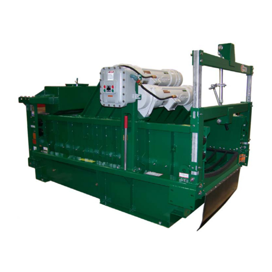
SECTION 1 - INTRODUCTION OVERVIEW This manual provides instructions for installing, operating, and maintaining the Derrick HyperPool shaker (Figure 1-1). The manual is divided into several sections to assist the user in readily accessing the information. Persons responsible for transporting, installing, operating, or performing maintenance on this equipment are required to read and understand the instructions provided in this manual. -
Page 10: Equipment Use
Box, weir, and weir bypass feeders are available, as well as desanders and desilters. Feed slurry may be introduced into the HyperPool shaker through the feeder if so equipped. The feeder evenly distributes slurry across the entire width of the screen frame. The hopper attached to the underside of the unit captures liquid underflow passing through the screen bed. - Page 11 INTRODUCTION Figure 1-4. Screen Frame Assembly The vibrator motors are attached directly to the screen frame and positioned over the screening bed to maximize the G-forces transferred to the screen surfaces. Float mounts isolate the vibratory motion of the screen frame from the support structure. The adjustable while drilling (AWD) mechanism is a manually operated jack screw that allows the operator to adjust the screen bed angle between +2°...
- Page 12 Feeders Box and weir bypass feeders are available for the HyperPool shaker. A brief description and sketch of each feeder is presented in Figure 1-6. The rear surface of the feeder is imprinted with 8”, 10”, and 12” (203mm, 254mm, and 305mm) pipe targets for locating the customer feed connection.
- Page 13 INTRODUCTION Box Feeder The box feeder receives and distributes feed slurry evenly across the screen frame. Slurry may be received either directly from the process stream or from a desilter collection pan. Weir Bypass Feeder The weir bypass feeder is divided into inlet and outlet tanks. This design allows the inlet slurry to rise in the inlet tank until sufficiently high to overflow into the outlet section.
- Page 14 INTRODUCTION Desilter and Desander (Cont’d) Figure 1-7. 4” Hydrocyclone Desilter Components Figure 1-8. 10” Hydrocyclone Desander Components 15 Jun 12 HyperPoolShaker...
-
Page 15: Product Support
INTRODUCTION PRODUCT SUPPORT Derrick offers 24-hour per day, 7-day per week product support. Product support includes screen replacement / ordering information and repair / replacement parts and service for the entire product line. Refer to the following table for the parts / service center nearest you. -
Page 17: Safety
SECTION 2 - SAFETY INTRODUCTION This section contains a summary of WARNINGS used in this manual and a list of material safety data sheets applicable to the equipment. The HyperPool shaker has been designed to perform the stated functions safely. WARNINGS... - Page 18 SAFETY Equipment Handling WARNING! USE SPREADER BARS TO PREVENT DAMAGE WHEN LIFTING THE EQUIPMENT. WARNING! TO ENSURE PROPER BALANCE AND ORIENTATION WHEN UNIT IS RAISED AND PREVENT DAMAGE TO COMPONENTS, ATTACH LIFTING SLING ONLY AT DESIGNATED LIFT POINTS. DO NOT ATTEMPT LIFTING BY ATTACHMENT TO MOTOR OR ANY OTHER LOCATION.
-
Page 19: Material Safety Data Sheets (Msdss)
The MSDSs listed below apply to products used in the manufacture of the Derrick equipment. Where shown, dates are current as of the publication date of this manual. The latest MSDSs may be obtained from the product manufacturer. -
Page 21: Installation
SECTION 3 - INSTALLATION GENERAL This section describes the recommended installation procedure for the Derrick HyperPool shaker. The equipment is shipped partially assembled to comply with shipping height restrictions. Installation of the desilter and desander, if included, is recommended before final placement of the equipment. -
Page 22: Installation Sequence
INSTALLATION INSTALLATION SEQUENCE Following is the sequence of steps for installing the HyperPool shaker. The sequence presented may vary depending on selected options, the user’s facilities, and previous experience with this type of equipment. 1. Read and understand all safety information in Section 2 before installing and operating this equipment. -
Page 23: Moving/Positioning The Equipment
INSTALLATION Figure 3-1 Recommended Clearances - HyperPool Shaker MOVING/POSITIONING THE EQUIPMENT WARNING! USE SPREADER BARS TO PREVENT DAMAGE WHEN LIFTING THE EQUIPMENT. WARNING! TO ENSURE PROPER BALANCE AND ORIENTATION WHEN UNIT IS RAISED AND PREVENT DAMAGE TO COMPONENTS, ATTACH LIFTING SLINGS ONLY TO LABELED LIFTING POINTS. DO NOT ATTEMPT LIFTING BY ATTACHMENT TO ANY OTHER LOCATION. - Page 24 INSTALLATION MOVING/POSITIONING THE EQUIPMENT (CONT’D) While the HyperPool shaker is still mounted on the shipping skid, the unit may be transported on the ground using a forklift. After the machine is removed from the shipping skid, an overhead- lifting device is required.
-
Page 25: Desilter And Desander Installation
INSTALLATION DESILTER AND DESANDER INSTALLATION While the HyperPool mud cleaner is fully assembled and tested prior to shipment, shipping restrictions that limit the overall height of equipment often require separation of the desilter and desander for shipment. The units are then skid-mounted for shipment with the basic machine. Refer to Section 4 for operating information on the desander and desilter. - Page 26 INSTALLATION Installation Procedure (Cont’d) Figure 3-3. Desilter Lift Points and Shipping Bracket Installation 4. Carefully lift desilter free of shipping skid. Orient desilter so that open end of discharge pipe is aligned with facility pipe. 5. Carefully guide desilter downward into notches of collection pan mounting brackets (Figures 3-4 and 3-5), and align with bracket mounting holes.
-
Page 27: Equipment Leveling
Figure 3-5. Desilter Mounting Details EQUIPMENT LEVELING To ensure even distribution of feed slurry across the screen panels, the HyperPool shaker must be properly leveled. Leveling along the length and width of the unit is shown for a typical machine in Figure 3-6. -
Page 28: Mounting And Securing Equipment
INSTALLATION MOUNTING AND SECURING EQUIPMENT WARNING! GRINDING, BURNING, OR WELDING WILL PRODUCE HAZARDOUS GASES AND DUST. ALWAYS WEAR PROPER PERSONAL PROTECTIVE EQUIPMENT (PPE) WHEN PERFORMING ANY OF THESE PROCEDURES. After completing assembly and leveling, the equipment may be welded to the deck or bolted with at least 5/8”... -
Page 29: Feed And Discharge Connections
INSTALLATION FEED AND DISCHARGE CONNECTIONS When configured as a mud cleaner, the HyperPool shaker is equipped with a round desilter having 4” hydrocyclones and desanders having 10” hydrocyclones. Desilters have clusters of 14, 16, or 20 hydrocyclones depending on customer requirements, and desanders have two or three 10”... -
Page 30: Electric Power Connections
INSTALLATION Feeder Connection (Cont’d) Figure 3-9. Feed Pipe Targets Collection Pan Bypass The collection pan outlet discharges directly into the feeder. An 8” (203mm) bypass outlet is ® provided on the underside of the collection pan to divert the feed, if necessary. A Victaulic and coupling is used to close the bypass opening. - Page 31 INSTALLATION WARNING! VIBRATOR MOTOR MUST BE OPERATED AT THE DESIGNATED SUPPLY VOLTAGE. WARNING! HIGH VOLTAGE MAY BE PRESENT. BE SURE FUSED DISCONNECT SUPPLYING ELECTRICAL POWER TO THIS EQUIPMENT IS OPEN. LOCK OUT AND TAG OUT POWER SUPPLY TO PREVENT ACCIDENTAL APPLICATION OF POWER WHILE MAKING ELECTRICAL CONNECTIONS.
-
Page 32: Screen Panel Installation
INSTALLATION SCREEN PANEL INSTALLATION The HyperPool shaker is equipped with the screen panel compression system. To prevent damage to screen panels, the machine is shipped without panels installed. Installation of screen panels for the first time is described in the following procedure. Prior to installing screen panels, remove all packing and shipping materials from the bed of the screen frame. -
Page 33: Machine Startup
INSTALLATION Screen panel notch engaged with locator Compressing screen panel Fully installed panel. Note downward curve into intimate contact with screen bed 6. Repeat procedure for three remaining screen panels. MACHINE STARTUP Refer to Section 4 for initial startup and operating procedures for the HP-704 shaker. WARNING! DO NOT ATTEMPT TO OPERATE MACHINE WITH SHIPPING BRACKETS INSTALLED. -
Page 35: Operating Instructions
PERSONNEL ARE CLEAR OF EQUIPMENT. INITIAL STARTUP Perform the Initial Startup procedure when the HyperPool shaker is being started for the first time, following parts replacement, or when equipment has been removed from service for an extended period. Refer to the following table for initial startup instructions. -
Page 36: Normal Startup
OPERATING INSTRUCTIONS NORMAL STARTUP The following procedure shall be performed at each machine startup: Step Procedure Verify that all personnel are clear of shaker before applying electric power to equipment. Closed fused disconnect to apply power to shaker. Press green START pushbutton to apply electric power to the vibrator motors. Allow motors to reach operating temperature (about 5 minutes). -
Page 37: Desilter And Desander Operation
OPERATING INSTRUCTIONS DESILTER AND DESANDER OPERATION To ensure equal distribution of feed material to each cone, the incoming feed slurry is introduced into the feed manifold, which contains 20 outlet ports equally spaced around its circumference. Ten outlets are positioned on each side of the discharge pipe to maintain balance. When a round desilter is outfitted with a full complement of cones, all 20 positions are filled. - Page 38 OPERATING INSTRUCTIONS “Roping” “Roping” is a term applied to a solid discharge stream (Figure 4-2) flowing from the hydrocyclones. This undesirable discharge pattern results from overloading the apex opening with solids, thereby preventing air from entering the cone. Due to the apex blockage, feed material entering the cone can no longer move downward and, therefore, flows directly out the upper discharge at the top of the cone.
- Page 39 OPERATING INSTRUCTIONS Figure 4-3. Hydrocyclone Spray Patterns Spray Pattern Versus Performance The three spray patterns are interpreted as follows: TOO WIDE - Spray angle greater than 30° with a hollow center. In normal operation, this pattern is undesirable. This spray pattern indicates that the exit diameter of the apex is too large, and an excessive amount of liquid discharges along with the solids flowing from the bottom of the cone.
-
Page 40: Awd Operation
OPERATING INSTRUCTIONS Recommended Operating Pressures Recommended operating pressures for the hydrocyclone desilter and desander are listed in the following table. Recommended Desilter/Desander Operating Pressures - 75’ Head Inlet Pressure Mud Weight (PPG) Specific Gravity Operating Pressure (PSI) 8.33 1.00 9.00 1.08 10.00 1.20... -
Page 41: Angle Adjustment
OPERATING INSTRUCTIONS Figure 4-4. Screen Frame Pooling Area ANGLE ADJUSTMENT The angle of the discharge end of the screen frame is infinitely adjustable within the equipment’s available range. To adjust the AWD, proceed as follows: WARNING! BE SURE THAT ALL PERSONNEL ARE CLEAR OF MACHINE BEFORE ADJUSTING ANGLE OF SCREEN BED. -
Page 42: Pool Configuration
OPERATING INSTRUCTIONS POOL CONFIGURATION Extensive testing has shown that the most efficient pool configuration maximizes use of the available screen area. In general, the pool should cover all screen panels except for the discharge screen, which is the last screen on the screen frame. The AWD allows the operator to easily change the angle of elevation in rapid response to ever- changing conditions and feed rates of the slurry. -
Page 43: Screen Retention System Operation
OPERATING INSTRUCTIONS SCREEN RETENTION SYSTEM OPERATION Proper screen functioning depends on secure retention and full contact with the screen bed. Be sure that each screen panel is secure by verifying that all screen panels compressed into conformance with the concave screen bed. Refer to Section 5 for screen replacement and maintenance procedures and to Section 6 for detailed description, operation, and repair of the system. -
Page 45: Maintenance
GENERAL This section contains routine maintenance, inspection, screen panel replacement, and parts replacement for the HyperPool shaker. Routine maintenance will ensure maximum life and trouble-free operation. While the maintenance schedule presented in this section is flexible, modifications should be based on experience with operating the equipment at your facilities. A maintenance log (see Section 9) should be kept to help establish a routine maintenance schedule, as well as to monitor and adjust the schedule as necessary throughout the equipment’s... -
Page 46: Screen Frame
MAINTENANCE ROUTINE MAINTENANCE (CONT’D) ROUTINE MAINTENANCE Action Frequency Inspect entire machine for evidence of coating damage, including exposed base metal, corrosion, deep scratches, or other voids. Repair Weekly damaged areas in accordance with coating manufacturers’ specifications (refer to Section 2). Lubricate AWD jack screw assembly using Dura-Lith EP, Mobilux EP, or Quarterly equivalent grease. - Page 47 MAINTENANCE SCREEN FRAME MAINTENANCE Action Frequency Inspect float mounts for excessive sag (greater than 1 inch / 25.4 mm) and/or signs of deterioration or damage. If excessive sag is found, clean excess buildup of process material from screen frame to reduce Monthly or as loading on float mounts.
-
Page 48: Screen Panel Replacement
MAINTENANCE SCREEN FRAME (CONT’D) Figure 5-1. Screen Frame Inspection and Maintenance SCREEN PANEL REPLACEMENT Use the following procedure when changing screen panels. If installing panels for the first time, follow only the instructions under Installation. Screen panel replacement is done with the installer on the compression side of the screen frame. - Page 49 MAINTENANCE 5. Press handle downward to release pawl from positioning gear tooth, and lift pawl from tooth. 6. Raise handle upward to retract compression pins. 7. Remove screen panel. 8. Inspect screen bed materials for wear and damage. If damage or excessive wear is found, replace bed materials in accordance with Screen Bed Material Replacement in this section.
- Page 50 MAINTENANCE Installation (Cont’d) Fully installed panel. Note downward curve into intimate contact with screen bed 3. Repeat procedure for three remaining screen panels. SCREEN BED MATERIAL REPLACEMENT The bed materials (Figure 5-2) should be replaced if inspection reveals damage or deterioration. To replace any of the bed materials, proceed as follows: 1.
-
Page 51: Vibrator Motors
MAINTENANCE VIBRATOR MOTORS Removal, installation, parts replacement, and troubleshooting procedures for the vibrator motors are included in Section 7. AWD JACK MAINTENANCE The AWD jack requires periodic lubrication and occasional adjustment of the spring plunger. Refer to Routine Maintenance at the beginning of this section for periodic lubrication instructions. If the ratchet action becomes noticeably imprecise or the pawl fails to latch during jack handle movement, the spring plunger should be adjusted as follows: 1. - Page 52 MAINTENANCE HYDROCYCLONE REMOVAL AND INSTALLATION (CONT’D) Figure 5-4. Hydrocyclone Removal Temporary Removal WARNING! WHEN REMOVING CONE FROM AN OPERATING DESILTER, BE SURE THAT SHUTOFF VALVE IS CLOSED OR DESILTER IS SHUT DOWN BEFORE RELEASING SNAP COUPLINGS. WARNING! ALWAYS WEAR SAFETY GLASSES WHEN REMOVING HYDROCYCLONES FROM A PRESSURIZED DESILTER.
- Page 53 HYDROCYCLONES IN A PRESSURIZED DESILTER. ® 1. If Victaulic caps (Derrick part number VIC-2-60) were installed on manifold ports, release snap couplings and remove caps. 2. Slide snap coupling gasket on end of manifold pipe. 3. Align inlet pipe of hydrocyclone with manifold pipe, and center gasket between the snap coupling grooves in hydrocyclone and manifold pipe (Figure 5-6).
-
Page 54: Recommended Spare Parts
This list includes the components most susceptible to wear; however, all potential part replacements cannot be predicted. The complete spare parts inventory should be based on the user’s experience with similar equipment. RECOMMENDED SPARE PARTS - HYPERPOOL SHAKER Part No. Description... - Page 55 MAINTENANCE RECOMMENDED SPARE PARTS - HYPERPOOL SHAKER Part No. Description Consumable Qty 16848-12 Support Assembly, Side, 23”, Nitrile G0001973 Bolt Assembly, SGX Vibrator, 3/4-16 x 4” W/Washer G00012323 Pushbutton Assembly, Start, Green G0004136 Pushbutton Assembly, Stop, Red SQD-2510-MC03 Starter, Manual Thermal Element, 4.69A-5.18A, 380/400V &...
-
Page 57: Screen Retention System
The HyperPool shaker is identified as either right- or left-hand, which designates the screen compression side of the machine. This arrangement allows an operator to work from one side of the machine to install and remove screen panels. -
Page 58: Operation
SCREEN RETENTION SYSTEM OPERATION The retention system is operated by inserting the tensioning handle into the receptacle provided on the positioning gear and pressing the handle downward (Figure 6-2). The downward motion rotates cams on the keyed shaft that drive the retention pins outward against the screen panel edges. -
Page 59: Description
SECTION 7 - SGX VIBRATOR MOTOR DESCRIPTION Motion is generated by dual explosion-proof SGX vibrator motors and transmitted to the screen frame to separate and conveys solids over the screen panels. The SGX motor is rated for continuous duty with Totally Enclosed Non-Ventilated (TENV) construction and permanently lubricated, sealed bearings. -
Page 60: Repair Restrictions
Also, while under warranty, no repairs of any kind are permitted; the motor may not be opened for any reason. If the motor fails while under warranty, contact the Derrick Service department for assistance. The warranty will be void, if it is determined that the motor has been opened during the warranty period. -
Page 61: Storage
REPLACEMENT PARTS The cross-sectional view and parts list below include replacement parts that are available for the Derrick SGX vibrator motor. This information should be used to identify and order replacement or spare parts for the motor. 15 Jun 12... - Page 62 SGX VIBRATOR MOTOR REPLACEMENT PARTS (CONT’D) Ref. Dwg. 14274-00 REPLACEMENT PARTS - SGX MOTOR Description Part No. Bearing G0001960 Bearing Mount 14266-01 Junction Box Cover 12739-00 Terminal Block Assembly 11006-00-001 O-Ring, 5.250 x 0.070 G0003627 Bearing Spacer 14269-01 O-Ring, 7.90 x 0.070 PP1503 Weights, Outer Serial Number Req’d...
-
Page 63: Removal And Installation
Tool Kits Tool kits containing all necessary equipment for removing and installing motor bolts are available from Derrick. Kit part numbers are as follows: Part No. Description Kit No. G0003029 - 3/4” Hex Hd Bolt G0002020 Torque Wrench, 200-600 ft-lbs, 3/4”... -
Page 64: Vibrator Motor (Cont'd)
SGX VIBRATOR MOTOR Safety Be sure to follow the warnings listed below before, during, and after removal or installation of the vibrator motor. WARNING! MOTOR HOUSING BECOMES HOT DURING OPERATION AND MAY CAUSE SEVERE BURNS. DO NOT TOUCH MOTOR HOUSING DURING OR IMMEDIATELY AFTER MOTOR HAS BEEN OPERATING. - Page 65 SGX VIBRATOR MOTOR Mounting Hardware Installation Note! Due To High Torque Applied During Installation, Re-Use of Motor Mounting Hardware Is Not Recommended. All Hardware Components Should Be Replaced Whenever A Motor Is Removed. The motor is secured to the screen frame with 3/4” bolts. When installing the bolts, note that the 3/4”...
- Page 66 SGX VIBRATOR MOTOR Motor Positioning and Mounting 1 - Using overhead lifting device, position vibrator motor over screen frame. 2 - Position motor on screen frame and align mounting holes with screen frame. Insert bolts (without anti-seize compound applied) with hardened washers through motor holes from underside of screen frame.
-
Page 67: Electrical Connections
The Derrick vibrator motor must be operated at the required voltage and frequency. Refer to the data plate on the motor case for the motor’s voltage and frequency requirements. Prior to installing a new vibrator motor, verify that the electrical power configuration corresponds to the electrical requirements specified on the motor. - Page 68 SGX VIBRATOR MOTOR Connections to Motor The procedure below describes motor cord connections to the motor. If replacing a cable, tag all leads for identification before disconnecting old cable. The SGX motor uses either of the following connection styles: Terminal Block - Cord is fed through the side of the motor junction box and connected to a terminal block inside the junction box Power Connector - Cord is fed through the junction box cover, which contains a female power connector where connections are made.
- Page 69 SGX VIBRATOR MOTOR Figure 7-2. Motor Cord Connections to Terminal Block 15 Jun 12 7-11 HyperPoolShaker...
- Page 70 SGX VIBRATOR MOTOR Figure 7-3. RTV Sealant Application Power Connector Style 1. Remove cover from motor junction box, and discard O-ring (Figure 7-4). 2. Insert motor cord leads through junction box cover. 3. Match leads to power connector markings, and connect leads to terminals as shown. 4.
- Page 71 SGX VIBRATOR MOTOR Figure 7-4. Motor Cord Connections to Power Connector 6. Apply small amount of LubriPlate 5555, part number L0107-007, or UL-approved equivalent, to new O-ring, and install O-ring in groove of cover. 7. Align cover mounting holes with holes in junction box, ensure that O-ring remains in place, and install cover by engaging power connector plug and receptacle.
- Page 72 SGX VIBRATOR MOTOR Connecting Motor Cords To Starter Box Motor leads are connected to manual starters inside the starter box (Figure 7-5). Refer to the schematic diagram in Section 8 for additional assistance in connecting the vibrator motors. Connect the motor leads to the starters as follows: 1.
-
Page 73: Preventive Maintenance
The following bearing replacement procedure applies only to SGX motors that are no longer under warranty. During the warranty period the motor is not to be opened for any reason, as this will void the warranty. Contact the Derrick Service department for assistance if a motor fails while under warranty. - Page 74 SGX VIBRATOR MOTOR NOTE! Bearings in Derrick vibrator motors are custom designed with loose ® internal clearances and are packed with Mobilith SHC 100 grease to prolong life. Regardless of supplier, bearings must be packed with this grease or equivalent.
- Page 75 SGX VIBRATOR MOTOR Work Area Environment A well-lighted area with sufficiently large work-surface area is required to work on the motor. The work surface should be clean to prevent contamination of the new bearings and motor interior. Safety The following WARNINGS apply to the bearing replacement procedure. Be sure to read and understand these WARNINGS before proceeding.
- Page 76 SGX VIBRATOR MOTOR Bearing Removal The following procedure describes bearing removal for one side of the motor. Repeat the procedure for bearing at opposite end. 1 - Using a 5mm hex wrench, remove eight 2 - Remove cover, and remove O-ring using socket head cap screws securing cover to a dental pick or similar tool.
- Page 77 SGX VIBRATOR MOTOR 5 - Using a soft absorbent cloth, remove 6 - Using a torch with a diffused flame, gently excess lubricant from components. Do not heat spacer for no more than 10 seconds to use compressed air for cleaning as this may approximately 200°-230°F (93°-110°C) to drive contaminants into motor.
- Page 78 SGX VIBRATOR MOTOR Bearing Removal (Cont’d) 9 - Locate two threaded holes that accept 10 - Carefully thread jack screws into the two M8-1.25x70 socket head jack threaded holes in bearing mount, being screws. Jack screw holes are 180 degrees sure to avoid cross-threading.
- Page 79 SGX VIBRATOR MOTOR 13 - Using a soft absorbent cloth, remove 14 - Using a torch with a diffused flame, excess lubricant from interior of bearing gently heat inner bearing race for no more housing and inner bearing race. Do not than 10 seconds to approximately 200°- use compressed air for cleaning as this 230°F (93°-110°C) to facilitate removal.
- Page 80 SGX VIBRATOR MOTOR Bearing Installation (Cont’d) 3 - After heating inner bearing race, slide 4 - Orient longer, reduced diameter of bearing race onto motor shaft until bearing mount toward motor body. Align shoulder of race contacts bearing seat in clearance holes in bearing mount with rear of cavity.
- Page 81 SGX VIBRATOR MOTOR 7 - Using a torque wrench and 6mm hex bit, 8 - Using a bearing heater or torch with a alternately tighten all six cap screws to 250 diffused flame, gently warm spacer (no in. lbs. Coat motor shaft with grease more than 10 seconds) to approximately (included in bearing replacement kit).
-
Page 82: Troubleshooting
5mm hex bit, tighten screws to 115 in. lbs. TROUBLESHOOTING The troubleshooting procedures presented in the following chart are designed to assist in fault isolation and correction of defects in the Derrick SGX vibrator motor. Trouble Possible Cause Corrective Action Check that supply voltage agrees with motor data plate. - Page 83 * Derrick vibrator motors run with higher surface temperatures than standard industrial motors. Refer to the maximum temperature rise indicated on the motor data plate attached to the motor case or the motor data sheet included in this manual.
-
Page 85: Reference Drawings
SECTION 8 - REFERENCE DRAWINGS This section contains Derrick engineering drawings for the HyperPool shaker. These drawings are included to provide assistance in troubleshooting, repair, and parts ordering. Drawing No. Title - General Arrangement - HyperPool 17611-00 - Parts List – HyperPool 4 Panel... - Page 89 FLATNESS USED BY CUSTOMERS OR PROSPECTS OR THEIR AGENCIES IN THE ARRANGEMENT OR INSTALLATION OF DERRICK EQUIPMENT, OR BY VENDORS IN QUOTING ON OR IN THE SUPPLY OF PARTS OR ASSEMBLIES TO DERRICK , OR BY OTHERS FOR THE SPECIFIC REASON OUTLINE IN THE TRANSMITTAL WHETHER WRITTEN OR VERBAL.
- Page 91 DERRICK...
- Page 111 **** FOR MAGNETIC STARTER OVERLOAD INFO REFER TO THE ELECTRICAL PARTS LIST THAT IS FOUND ON THE EQUIPMENTS GENERAL ARRANGEMENT DRAWING. Derrick®, Flo-Line®, FLC 2000™, Flo-Line Scalper™, Pyramid®, Sandwich Screens®, DE-1000™, Hi-G™, Vacu-Flo™, GBG™, PMD™, PWP™, SWG™, DC™, DF™, DX™, and GS™, are trademarks of Derrick Corporation.
- Page 113 This section should be used by operating and maintenance personnel to record historical information gathered during the installation and operation of the Derrick equipment. If properly kept, the log will be useful for altering maintenance intervals and intercepting trends that may indicate the need for changing operating procedures.
- Page 114 INSTALLATION & MAINTENANCE LOG 15 Jun 12 HyperPoolShaker...
-
Page 115: Installation And Maintenance Log
INSTALLATION AND MAINTENANCE LOG 15 Jun 12 HyperPoolShaker... - Page 116 INSTALLATION & MAINTENANCE LOG 15 Jun 12 HyperPoolShaker...
- Page 117 INSTALLATION AND MAINTENANCE LOG 15 Jun 12 HyperPoolShaker...
- Page 118 INSTALLATION & MAINTENANCE LOG 15 Jun 12 HyperPoolShaker...
Need help?
Do you have a question about the HYPERPOOL SHAKER and is the answer not in the manual?
Questions and answers
Starter and motor connection diagram.