Table of Contents
Advertisement
Operating instructions
Motor-driven Metering Pump
alpha ALPc
EN
Please carefully read these operating instructions before use. · Do not discard.
The operator shall be liable for any damage caused by installation or operating errors.
The latest version of the operating instructions are available on our homepage.
Part no. 986353
Original operating instructions (2006/42/EC)
BA ALP 015 08/18 EN
Advertisement
Table of Contents
Troubleshooting

Subscribe to Our Youtube Channel
Related Manuals for ProMinent alpha ALPc 1001


Summary of Contents for ProMinent alpha ALPc 1001
- Page 1 Operating instructions Motor-driven Metering Pump alpha ALPc Please carefully read these operating instructions before use. · Do not discard. The operator shall be liable for any damage caused by installation or operating errors. The latest version of the operating instructions are available on our homepage. Part no.
- Page 2 Supplemental directives Supplementary information This provides important information relating to the correct operation of the unit or is intended to make your work easier. Fig. 1: Please read! Read the following supplementary information in its entirety! You will benefit more from using Safety Information the operating instructions should you already Safety information is identified by pictograms -...
-
Page 3: Table Of Contents
Table of contents Table of contents Identity code..........................5 Safety chapter......................... 7 Storage, Transport and Unpacking..................12 Overview of equipment......................13 Functional description......................14 Power end........................14 Liquid End........................14 Assembly..........................15 Installation, hydraulic......................16 Installing hose lines...................... 17 7.1.1 Installation of the suction and discharge line............ - Page 4 Table of contents Declaration of Conformity for Machinery................49...
-
Page 5: Identity Code
Seal material 2 Without valve spring, with bleed valve 3 with 2 valve springs (approx. 0.1 bar, material 1.4571), with bleed valve Hydraulic connector 0 Standard connection in line with technical data Design 0 with ProMinent logo M modified Electrical connection... - Page 6 Identity code alpha product range, version c A 230 V , 50/60 Hz, 2 m European B 230 V, 50/60 Hz, 2 m Swiss C 230 V, 50/60 Hz, 2 m Australian D 115 V , 50/60 Hz, 2 m USA Accessories no accessories with foot and injection valve, 2 m PVC suction line, 5 m...
-
Page 7: Safety Chapter
Observe the general limitations with regard and this can result in to viscosity limits, chemical resistance and serious injuries. density - see also ProMinent ® Resistance List in the Product Catalogue or at CAUTION Denotes a possibly www.prominent.com! - Page 8 Customer Service department refers to service Troubleshooting Technical personnel, technicians, who have received proven training electrical technician, and have been authorised by ProMinent or Pro‐ instructed person, Maqua to work on the system. service Explanation of the terms: Technical personnel...
- Page 9 Safety chapter Safety information WARNING! WARNING! Warning of hazardous feed chemical Should a dangerous feed chemical be Warning about personal and material used: it may escape from the hydraulic damage components when working on the The pump can start to pump, as soon pump, material failure or incorrect han‐...
- Page 10 – Take into account the resistance of the wetted materials and the CAUTION! ProMinent Resistance List when selecting the feed chemical - see Danger from incorrectly operated or the ProMinent Product Catalogue inadequately maintained pumps or visit ProMinent.
- Page 11 Customer should only remove the dosing head pressure. Adhere to the material safety data in accordance with the "Repair" chapter. sheet for the feed chemical. Only the ProMinent Service department are authorised to remove the housing. Sound pressure level Ensure that all protective equipment is properly Sound pressure level LpA <...
-
Page 12: Storage, Transport And Unpacking
Storage, Transport and Unpacking Storage, Transport and Unpacking CAUTION! Safety Information Danger of material damage The device can be damaged by incor‐ WARNING! rect or improper storage or transporta‐ tion! Only return metering pumps for repair – The unit should only be stored or in a cleaned state and with a flushed transported in a well packaged liquid end - refer to "Decommissioning! -
Page 13: Overview Of Equipment
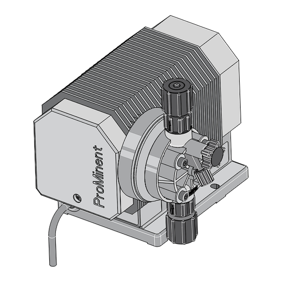
Overview of equipment Overview of equipment P_ALP_0007_SW Fig. 3 Cover Bypass hose nozzle Motor mounting Suction connector Housing Dosing head Pressure connector Eccentric disc with scale Bleed valve 10 Latched slide... -
Page 14: Functional Description
Functional description Functional description Power end The cam for the stroke movement is guided in an eccentric disc. Pumps of this size do not therefore require conventional return springs – the suction and pressure stroke are positively driven. The stroke length can be adjusted by a latched slide (9) from 100% to 0 in increments of 10%. -
Page 15: Assembly
Assembly Assembly WARNING! The IP 23 protection against moisture and accidental contact only applies to horizontal pump bases with vertically installed pumps. CAUTION! When assembling the pump, ensure that there is sufficient room around the pump for operation, maintenance, repairs and quick disconnection of the mains plug. -
Page 16: Installation, Hydraulic
- by unauthorised persons. see the ProMinent Product Cata‐ – Depressurise the system before logue or visit www.prominent.com. commencing any work on hydraulic parts. -
Page 17: Installing Hose Lines
Only fit parts to metering pumps, – Always adhere to the maximum which have been tested and rec‐ permissible operating pressure of ommended by ProMinent. all hydraulic components - please refer to the product-specific oper‐ ating instructions and system doc‐ umentation. - Page 18 Installation, hydraulic CAUTION! Hazardous feed chemicals can escape Align the pipes so that the metering pump and the liquid end can be Hazardous or extremely aggressive removed from the side if necessary. feed chemicals can leak out in the event that the metering pump is removed from the installation.
- Page 19 Installation, hydraulic Installing hose lines Cut off the ends of the hoses at right angles. Pull the union nut (20) and clamp ring (21) over the hose (24) - see figure Ä ‘Installing hose lines’ on page 18 . Push the hose end (24) up to the stop over the nozzle (4) and widen, if neces‐...
-
Page 20: Installation Of Metering Pumps With Bleed Valve
Installation, hydraulic 7.1.2 Installation of metering 7.1.3 Basic installation notes pumps with bleed valve Safety notes Safety notes CAUTION! CAUTION! Danger from rupturing hydraulic com‐ – All the installation and safety notes ponents for metering pumps without bleed Hydraulic components can rupture if valves also apply. - Page 21 Installation, hydraulic P_MAZ_0001_SW Fig. 5: Standard installation Main line Storage tank...
- Page 22 Installation, hydraulic Legend for hydraulic diagram Symbol Explanation Symbol Explanation Metering pump Foot valve with mesh Injection valve Level switch Multifunctional valve Manometer...
-
Page 23: Electrical Installation
Electrical installation Electrical installation WARNING! WARNING! Danger of an electric shock Danger of electric shock Only trained and authorised personnel Mains voltage may be present inside may install the pump. the pump housing. – If the pump housing has been damaged, disconnect it from the mains immediately. -
Page 24: Start Up
(1) closed and the of the materials that come into safety screw tightly screwed in. contact with the medium when selecting the feed chemical - refer to the ProMinent ® Resistance List in the Product Catalogue or at www.prominent.com.de/... - Page 25 Start up Starting up the metering pump Ä ‘Filling the liquid Fill the liquid end - end’ on page 26 . Reliable metering cannot be guar‐ – Check the pump connectors and con‐ anteed after the metering pump nections for leak-tightness. has been idle for some time, as the feed chemical can crystallise in Check the suction valve and discharge...
- Page 26 Start up Filling the liquid end With liquid ends with bleed valve: With liquid ends without bleed valve: Connect the suction and discharge line to the liquid end. Connect the suction line to the liquid end but not yet to the discharge line. Connect the return line.
- Page 27 Start up Tightening torque Data Value Unit Tightening torque for screws: 4.5 ... 5.0 Nm Adjusting the stroke length Remove the cover (1). Replace the latched slide (9) onto the eccentric disc. Set the eccentric disc (10) to 100 %. Lock the latched slide in place.
-
Page 28: Maintenance
Maintenance Maintenance WARNING! It is mandatory that you read the safety information and specifications in the "Storage, Transport and Unpacking" chapter prior to shipping the pump. CAUTION! Warning of feed chemical spraying around Feed chemical can spray out of the hydraulic components if they are manipulated or opened due to pressure in the liquid end and adjacent parts of... - Page 29 Maintenance Standard liquid ends: Interval Maintenance work Personnel Quarterly* Check the metering diaphragm for damage** - refer to Technical personnel "Repair". Check that the hydraulic lines are fixed firmly to the liquid end. Check that the suction valve and discharge valve are fitted tightly.
- Page 30 Maintenance Liquid ends with bleed valve: Interval Maintenance work Personnel Quarterly* In addition: Technical personnel Check that the bypass line is fixed firmly to the liquid Check that the bleed valve is tight. Check the discharge and bypass line for kinks Check that the bleed valve is operating correctly.
-
Page 31: Repairs
Repairs Repairs Safety notes CAUTION! WARNING! Warning of feed chemical spraying around Danger of an electric shock Feed chemical can spray out of the Unauthorised repairs inside the pump hydraulic components if they are can result in an electric shock. manipulated or opened due to pressure in the liquid end and adjacent parts of For this reason repairs inside the pump... -
Page 32: Replacing The Diaphragm
Repairs 11.2 Replacing the diaphragm Fig. 8 Set the eccentric disc (10) to "0". If necessary take protective measures. Adhere to the safety data sheet for the feed chemical. Ensure that the system is at atmospheric pressure. The latched slide (9) cannot lock in this position. - Page 33 Repairs Fig. 10 Pump types 1001, 1002, 1004, 1008, 0707, 0417: (Diaphragm WITHOUT holes, threaded Loosen the diaphragm (15) by turning to rod without hexagonal nut) the left - use pliers if necessary. If the threaded rod (16) has come loose together with the diaphragm, unscrew the diaphragm from the threaded rod (turning to the left) - using pliers if nec‐...
- Page 34 Repairs Fig. 11 Pump type 0230: (Diaphragm WITH holes, threaded rod with hexagonal nut) Use a flat wrench (SW 8) to loosen the hexagonal nut (arrow) in front of the connecting rod by about one turn. Loosen the diaphragm (15) with the backplate (14) and the threaded rod (16) from the motor mount (2) by turning it to the left.
- Page 35 Repairs Concluding the work With PP types with bleed valve: Allow CAUTION! the cover of the liquid end to rest in the There should be no gap visible dosing head, then press the grip on the between the diaphragm and the bleed valve into the dosing head.
-
Page 36: Replacing The Complete Dosing Head
Repairs Tightening torque Data Value Unit Tightening torque for screws: 4.5 ... 5.0 Nm 11.3 Replacing the complete dosing head The bleed valve is open on – delivery. Re-tighten the bleed valve (5) after – priming and bleeding. Check that the suction and dis‐ –... -
Page 37: Troubleshooting
Troubleshooting Troubleshooting Safety notes WARNING! WARNING! Risk of fingers being crushed – Only adjust the stroke length when Warning of dangerous or unknown feed the pump is switched off. chemical – Only operate the metering pump Should a dangerous or unknown feed with the cover (1) closed and the chemical be used: It may escape from safety screw tightly screwed in. -
Page 38: Faults And Troubleshooting
Troubleshooting 12.1 Faults and troubleshooting Fault description Cause Remedy Personnel Pump does not Minor crystalline Take suction hose out of the Technical prime in spite of deposits on the ball storage tank and thoroughly flush personnel full stroke motion seat due to the valves out the liquid end and bleeding. -
Page 39: All Other Faults
12.2 All other faults Please contact the responsible ProMinent branch or representative! -
Page 40: Decommissioning And Disposal
Decommissioning and disposal Decommissioning and disposal 13.1 Decommissioning CAUTION! Decommissioning Warning of feed chemical spraying around WARNING! Feed chemical can spray out of the Danger from chemical residue hydraulic components if they are manipulated or opened due to pressure There is normally chemical residue in in the liquid end and adjacent parts of the liquid end and on the housing after the system. -
Page 41: Disposal
Decommissioning and disposal 13.2 Disposal In accordance with the European Directive 2012/19/EU on waste electrical and electronic equipment, this device features the symbol showing a waste bin with a line through it. The CAUTION! device must not be disposed of along with domestic waste. -
Page 42: Technical Data
Technical data Technical data Performance data for alpha, version c Type Minimum Minimum Stroke Con‐ Suction Pri‐ Max‐ Max. pump capacity pump capacity rate nector lift* ming imum permis‐ size lift** per‐ sible at maximum at medium mis‐ priming back pressure back pressure out‐... - Page 43 Technical data Pump capacity was calculated using water and a metering pump warmed to operating temperature. With types 1001, 1002 and 1004, the pump capacity can fall to zero at 20% stroke length and back pressure of > 4 bar. Precision Data Value Unit...
- Page 44 Technical data Material specifications Design Dosing head Suction/pressure Seals Valve balls connector Polypropylene Polypropylene EPDM Ceramic Polypropylene Polypropylene FPM-B Ceramic Clear acrylic EPDM Ceramic Clear acrylic FPM-B Ceramic PVDF PVDF PTFE Ceramic Diaphragm with a PTFE coating. FPM = fluorine rubber. Electrical data Circuit breaker Tab.
- Page 45 Technical data Pump temperature, compl. Data Value Unit Storage and transport temperature -20 ... +60 °C Ambient temperature in operation (drive and control): -10 ... +45 °C Liquid end temperature, long-term* Data Value Unit Liquid end temperature -10 ... +35 °C * long term at max.
-
Page 46: Design Documents
Design Documents Design Documents Design documents, such as dimen‐ sional drawings, ordering data (exploded drawings), performance dia‐ grams ... are available in the relevant online version of these operating instructions on our website. When searching on the website, please use simply the 6-digit order number for these operating instructions - this can be found at the bottom left corner of the cover page. -
Page 47: Dimensional Drawings
Dimensional drawings Dimensional drawings Dimensional drawing of alpha ALPc Ø 70 177.6 41.7 Ø 50 35.9 P_ALP_0006_SW Fig. 13: Dimension drawing of ALPc - dimensions in mm... -
Page 48: Further Order Information
Replacement diaphragms for alpha c Type Part no. 1001, 1002, 1004, 1008 1000247 0707, 0417 1000249 0230 1000250 Further sources of information Further information on spare parts, accessories and options can be found in: the identity code the ProMinent ® Product Catalogue at www.prominent.com... - Page 49 EMC Directive (2014/30/EU) Harmonised standards EN ISO 12100:2010 applied, in particular: EN 809:1998 + A1:2009 + AC:2010 EN 61010-1:2010 EN 61000-6-2:2005 + AC:2005 EN 61000-6-3:2007 + A1:2011 + AC:2012 Date: 20/04/2016 You can download the Declaration of Conformity at www.prominent.com.
- Page 52 ProMinent GmbH Im Schuhmachergewann 5-11 69123 Heidelberg Germany Telephone: +49 6221 842-0 Fax: +49 6221 842-419 Email: info@prominent.com Internet: www.prominent.com 986353, 3, en_GB © 2013...
Need help?
Do you have a question about the alpha ALPc 1001 and is the answer not in the manual?
Questions and answers