Table of Contents
Advertisement
1
2
3
81503D_MHW_400-401_12-2010_ENG
400 / 401
SINGLE DISPLAY TEMPERATURE CONTROLLER WITH UNIVERSAL INPUT
GENERAL INDEX
Page
2
2
2
2
3
4
4
4
5
5
5
6
6
6
6
7
8
INSTALLATION AND
OPERATION MANUAL
Software Version 3.0x
Code 81503D / Edition 06 - 12/2010 ENG
4
5
6
7
8
9
The contents of each section are summarized
immediately following the section heading
9
10
13
13
14
14
14
15
15
16
17
1
Advertisement
Table of Contents

Subscribe to Our Youtube Channel
Related Manuals for gefran 400


Summary of Contents for gefran 400
-
Page 1: Table Of Contents
400 / 401 SINGLE DISPLAY TEMPERATURE CONTROLLER WITH UNIVERSAL INPUT INSTALLATION AND OPERATION MANUAL Software Version 3.0x Code 81503D / Edition 06 - 12/2010 ENG GENERAL INDEX Page Standard configuration menu Graphic symbols used Preliminary instructions General description Configuration and programming... -
Page 2: Graphic Symbols Used
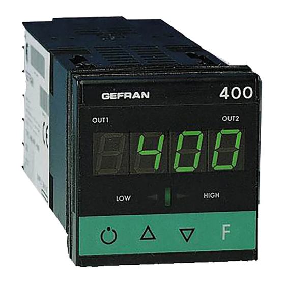
They have 4 keys, 4 digits display, 2 indicating LED’s menu driven configuration program for Windows and for 400 model, 3 indicating LED’s for 401 model and a the necessary cable to connect the instrument (see further 3 LED’s bar-graph. -
Page 3: Preliminary Warnings
N°. and Type of Inputs/Outputs available • Presence of the necessary options and accessories • Mains voltage supply Example: 400 – R – R – R – 0 Model 400 3 relay outputs Power supply 11...27Vac/dc • Before installing the instrument serie 400/401 on the control panel of the machine or host system, refer to the paragraph “Dimensions and Cut-out”... -
Page 4: Installation And Connection
• if the instrument is used in applications with risk of for correct installation of the instrument series damage to persons, machinery or materials, it is 400/401 into the machine control panel or the essential to connect it up to auxiliary alarm host system and for correct connection of the equipment. -
Page 5: Advice For Correct Installation For Emc
Direct Current. connection: - the voltage between neutral and earth must not be >1V GEFRAN S.p.A. declines all responsibility for - the Ohmic resistance must be < 6Ω; any damage to persons or property caused •... -
Page 6: Dimensions And Cut-Out
Example: 400 – x – x – x – 0 = 11...27Vac/dc 400 – x – x – x – 1 = 100...240Vac 81503D_MHW_400-401_12-2010_ENG... -
Page 7: Electrical Connections
Electrical Connections • Current transformer outputs / inputs • Inputs Generic user-configurable dc current • Linear (I) output linear input 0 ... 20mA, 4 ... 20mA Out2 (Al1) - relay 5A/250Vac - logic for OUT1 10V (6V/20mA) Rout=220Ω for OUT2 24V (10V at 20mA) Out1 (Main) dc voltage •... -
Page 8: Functions
3 • FUNCTIONS This section describes the use and functions of the displays, lighted indicators and buttons making up the controller operator interface. It therefore contains essential information for correct programming and configuration of the controllers. Operator interface LED flashes during software shutdown Indication of output states Display OUT 1 (Main);... -
Page 9: Standard Configuration Menu
4 • STANDARD CONFIGURATION MENU Setting Parameters Configurat. S.tu Autotuning Selftuning Softstart Default Custom continuous Enable selftuning, S. t v autotuning, softstart Proportional heating h. P b 10.0 range or hysteresis in 0 ... 999,9% f.s. regulation ON/OFF h. I t Integral heating time 0,00 ... -
Page 10: Configuration And Programming
5 • PROGRAMMING and CONFIGURATION LEVEL 1 DISPLAY Pressed for Software version P.V. approx. Process variable (display PV) 2 sec. Keep the F key pressed to scroll Setting parameters the menus Setpoint variable Release the F key to select the Input settings C.T. - Page 11 HY.2, HY.3 (only for model 400) PID cold x.xxx (*) InP: FLt, FLd, oFS, LoL, HIL PID hot / cold Out: ALn, A2t, A3t (only for model 400), rEL ON-OFF hot (*) not available for ON-OFF cold TC, RTD, PTC scales FLt, FLd, oFS stay at set value.
- Page 12 r.o.x MAIN logic output function, relay (OUT1) OUT 1 r. o . 1 HEAT (heating control output) Attribution of reference COOL (cooling control output) signal: HEAT, COOL, AL1, AL1 - alarm 1 AL2, AL3 AL2 - alarm 2 AL3 - alarm 3 [A.Hb mod. 401]) OUT 2 r.
-
Page 13: Alarms
If the Integral Time value is too long (Weak integral action), deviation between the controlled variable and the setpoint may persist. Contact GEFRAN for more information on control actions. 81503D_MHW_400-401_12-2010_ENG... -
Page 14: Tecnica Di Tune Manuale
8 • MANUAL TUNING A) Enter the setpoint at its working value. B) Set the proportional band at 0.1% (with on-off type setting). C) Switch to automatic and observe the behavior of the variable. It will be Process similar to that in the figure: Variable D) The PID parameters are calculated s follows: Proportional band Peak... -
Page 15: Self-Tuning
11 • SELF-TUNING The function works for single output systems (heating or cooling). The self-tuning action calculates optimum control parameter values during process startup. The variable (for example, temperature) must be that assumed at zero power (room temperature). The controller supplies maximum power until an intermediate value between starting value and setpoint is reached, after which it zeros power. -
Page 16: Technical Specifications
13 • TECHNICAL SPECIFICATIONS Display 4 digit green LED’s, digit height 10mm Keys 4 mechanical keys (Man/Aut, Raise, Lower, F) Accuracy 0.25% f.s. at 25°C ambient temperature Main input TC, RTD (Pt100), PTC 60mV Ri ≥ 1MΩ, 10V Ri ≥ 10KΩ, 20mA Ri = 50Ω Thermocouples IEC 584-1 (J, K, R, S, T, B, E, N) Cold junction error... -
Page 17: Accessories
OUT = 50mAac threading screws • RS232 / TTL interface cable for configuration of GEFRAN instruments N.B.: The RS232 interface for configuration from PC is supplied along with the programming software. Connect with the instrument powered and with inputs and outputs not connected. - Page 18 3 OUTPUT 1 Relay Logic OUTPUT 2 Relay Logic USCITA 3 / INGRESSO TA (solo per mod. 401) Relay Logic CT input 50mAac POWER SUPPLY 11...27Vac/dc 100...240Vac Please, contact GEFRAN sales people for the codes availability. 81503D_MHW_400-401_12-2010_ENG...
- Page 19 401 APPENDIX • SCHEDE INGRESSI / USCITE • INPUT/OUTPUT BOARDS • CARTES D’ENTREES/SORTIES • E/A-KARTEN • FICHAS ENTRADAS/SALIDAS • PLACAS DE ENTRADAS/SAÍDAS USCITA RELÉ (OUT3) RELAY OUTPUT (OUT3) SORTIE RELAIS (OUT3) RELAISAUSGANG (OUT3) SALIDA RELÉ (OUT3) SAÍDA DE RELÉ (OUT3) PROFILO Questa scheda supporta la funzione di uscita prevista come OUT3 nello strumento 401.
- Page 20 USCITA LOGICA (OUT3) LOGIC OUTPUT (OUT3) SORTIE LOGIQUE (OUT3) LOGIKAUSGANG (OUT3) SALIDA LÓGICA (OUT3) SAÍDA LÓGICA (OUT3) PROFILO Questa scheda supporta la funzione di uscita prevista come OUT3 nello strumento 401. Adatta a pilotare ingressi logici, applicazione tipica per interfaccia verso interruttori statici (GTS). La schedina è...
- Page 21 INGRESSO TA (OUT3) CT INPUT (OUT3) ENTREE TA (OUT3) STROMWANDLER-EINGANG (OUT3) ENTRADA TA (OUT3) ENTRADA TA (OUT3) PROFILO Questa scheda supporta la funzione di ingresso da trasformatore amperometrico come alternativa ad OUT3 nello strumento 401. La schedina è automaticamente riconosciuta dallo strumento che abilita visibilità ed impostazione dei parametri relativi. PROFILE This board supports the current transformer input function as alternative to OUT3 on the 401 instrument.
Need help?
Do you have a question about the 400 and is the answer not in the manual?
Questions and answers