Advertisement
1 • INSTALLATION
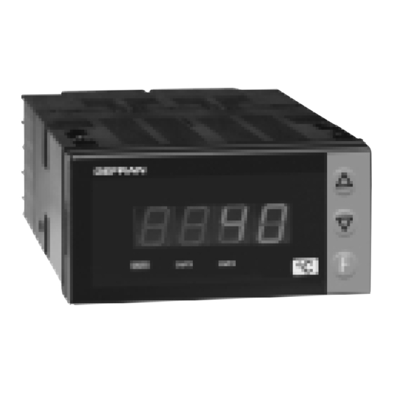
• Dimensions and cut-out: Panel mounting
76
72
30
36
52
9,5
Panel mounting:
Fix the device with the bracket provided before making any electrical connections.
To mount two or more devices side by side, use the cut-out dimensions shown above.
CE MARKING: EMC (electromagnetic compatibility) conformity to EEC Directive
89/336/CEE with reference to the generic Standard EN61000-6-2 (immunity in
industrial environments) and EN50081-1 (emission in residential environments).
BT (low voltage) conformity to Directive 73/23/CEE as modified by Directive 93/68.
MAINTENANCE: Repairs must be done out only by trained and specialized personnel.
Cut power to the device before accessing internal parts.
Do not clean the case with hydrocarbon-based solvents (Petrol, Trichlorethylene, etc.).
Use of these solvents can reduce the mechanical reliability of the device. Use a cloth
dampened in ethyl alcohol or water to clean the external plastic case.
SERVICE: GEFRAN has a service department. The warranty excludes defects caused
by any use not conforming to these instructions.
40T 72 PID
UNIVERSAL SINGLE DISPLAY HEAT CONTROL
69,5
83
!
For correct and safe
installation, follow the
instructions and observe
the warnings contained in
this manual.
USER'S MANUAL
SOFTWARE VERSION 1.0x
code 81761A / edition 05 - 06/04
2 • TECHNICAL SPECIFICATIONS
Display
Keys
Accuracy
Main input
Thermocouples
Cold junction error
RTD type (scale configurable within
indicated range, with or without decimal point)
Max. RTD line resistance
PTC type (on request)
Safety
°C / °F selection
Linear scale ranges
43
Control actions
pb
dt
di
Action
Control outputs
Limitation Max power heat / cool
Cycle time
Type of main output
Softstart
Fault power setting
Software turn-off function
Configurable alarms
Alarm masking
Relay contact
Logic output for static relays
Triac output
Fault settings
2-wire Transmitter Power Supply
(option)
Power supply
(not isolated from sensor input)
Faceplate protection
Working / Storage temperatures
Relative humidity
Installation
Weight
EMC conformity has been tested with the following connections
FUNCTION
TC input probe
"PT100" input probe
Power supply cable
Relay output cables
10
4 digit red LED's, digit height 14mm
3 mechanical keys (Raise, Lower, F)
0.2% f.s. at 25°C ambient temperature
TC, RTD (Pt100), PTC
60mV, Ri ≥ 500K; 20mA, Ri = 50Ω; 10V Ri < 20K
IEC 584-1 (J, K, R, S, T, B, E, N)
0,1° / °C
DIN 43760 (Pt100)
20Ω
990Ω, 25°C
detection of short circuit or opening of probes, LBA
alarm
Faceplate configurable
-1999 to 9999 configurable decimal point position
Pid, Autotune, on-off
0,0...999,9 %
0,00...99,99 min
0,00...99,99 min
heat or cool
on / off, pwm
0,0...100,0 %
0...200 sec
relay, logic
0,0...500,0 min
-100,0...100,0 %
Can be excluded
Up to 3 alarm functions assignable to an output
and configurable as: maximum, minimum,
symmetrical, absolute/relative, LBA
exclude on power-up
NO (NC) 5A, 250V
power supply > 18Vac/dc,
Rout = 560Ω (6Vmin / 20mA)
20...240Vac ±10%, 2Amax, load I
2
t = 128A
Alarm states can be configured in probe fault
condition
18V ±10% 50mA
1.2V for potentiometer > 100 Ω (version P77)
11...27Vdc, 18...27Vac ±10%, 50/60Hz, 4,5VA
IP65
0 to 50°C / -20 to 70°C
20 to 85%, non-condensing
Panel mounting
110g for the complete version
CABLE
LENGTH USED
0,8 mm
2
compensated 5 mt
1 mm
3 mt
2
1 mm
2
1 mt
1 mm
2
3,5 mt
2
s
Advertisement
Table of Contents

Related Manuals for gefran 40T 72 PID


Summary of Contents for gefran 40T 72 PID
- Page 1 TC input probe 0,8 mm compensated 5 mt SERVICE: GEFRAN has a service department. The warranty excludes defects caused “PT100” input probe 1 mm 3 mt by any use not conforming to these instructions.
- Page 2 3 • DESCRIPTION OF FACEPLATE “Raise” and “Lower” keys: PV display: Indication of process variable •• These keys are used for any operation that Indication of ‘HI’ or ‘Lo’ out of range •• Indication of requires a numerical parameter to be raised or open circuit (br) or short circuit (Er) ••...
-
Page 3: Standard Configuration Menu
5 • Standard Configuration Menu Setting Parameters Configurat. S.tu Autotuning Selftuning Softstart Default Custom continuous Enable selftuning, autotuning, softstart Proportional band 10.0 for heating or hysteresis 0 ... 999,9% f.s. in regulation ON/OFF Integral heating time 0,00 ... 99,99 min Derived heating time 0,00 ... -
Page 4: Programming And Configuration
6 • PROGRAMMING and CONFIGURATION LEVEL 1 DISPLAY Pressed for Software version approx P.V. Process variable (display PV) 2 sec. Setting parameters Setpoint variable Input settings Alarm setpoint 1 Output settings Alarm setpoint 2 PASS Password Alarm setpoint 3 Keep the F key pressed to browse the menus. - Page 5 • InP Input settings Configurat. CtrL Type of control Default Custom P heat Maximum limit of main min…max scale of input Type of control 1000 P cool input scale selected in t.P [0...27] P heat / cool PI heat PI cool PI heat / cool +16 disable parameters PID heat...
- Page 6 r.o.x MAIN logic output function, relay (OUT1) OUT 1 HEAT (heating control output) Attribution of COOL (cooling control output) reference signal: HEAT, AL1 - alarm 1 COOL, AL1, AL2, AL3 AL2 - alarm 2 AL3 - alarm 3 OUT 2 LBA - alarm LBA Attribution of (AL1) OR (AL2)
-
Page 7: Technical Data
7 • ACCESSORIES • RS323 interface cable for configuration N.B.: the PC configuration cable is supplied with the programming software. WARNING: make the connection with the device powered and with inputs and outputs disconnected. • ORDER CODE Interface cables WSK-0-0-0 + CD Winstrum •... -
Page 8: Order Code
VAC. Resistors must be at least 2W); fit a 1N4007 diode in parallel with the coil of inductive loads that operate in DC. GEFRAN spa will not be held liable for any injury to persons and/or damage to property deriving from tampering, from any incorrect or...
Need help?
Do you have a question about the 40T 72 PID and is the answer not in the manual?
Questions and answers