
Related Manuals for Balluff BNI ECT-508-105-Z015


Summary of Contents for Balluff BNI ECT-508-105-Z015
- Page 1 BNI ECT-508-105-Z015 IP67 Module 8 IO-Link/Inputs/Outputs, 8 Inputs/Outputs User´s Guide...
-
Page 2: Table Of Contents
Required setting on the device Station alias Configuring IO-Link module 5.4. Bit mapping and function Inputs pin 4 Inputs pin 2 Outputs pin 4 Outputs pin 2 IO–Link modules Short circuit pin 4 / pin 2 Restart pin 4 / pin2 www.balluff.com... -
Page 3: Inputs Pin
Balluff Network Interface EtherCAT™ IO-Link state Sensor short circuit Display LED 5.5. Startup Configuration of the modules Validation Parameter server Upload flag on the IO-Link device Safe state 5.6. IO-Link parameterization Control Status Example - CoE setting Example - Read... -
Page 4: General
1.3. Symbols Note This symbol indicates general notes. Attention This symbol indicates a safety instruction that must be followed without exception. 1.4. Abbreviations Balluff Network Interface Standard input port EtherCAT™ Electromagnetic compatibility Functional ground Standard output port 1.5. Divergent views Product views and images can differ from the specified product in this manual. -
Page 5: Safety
Attention voltage Disconnect all power before servicing equipment. Note In the interest of product improvement, the Balluff GmbH reserves the right to change the specifications of the product and the contents of this manual at any time without notice. www.balluff.com... -
Page 6: First Steps
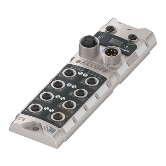
First steps 3.1. Module overview Overview BNI ECT-508-105-Z015 Mounting hole Port 7 (IO-Link, standard I/O) EtherCAT™-Port 2 OUT Port 6 (IO-Link, standard I/O) Display Port 4 (IO-Link, standard I/O) Power supply input Port 2 (IO-Link, standard I/O) Status LED: communication / module... -
Page 7: Mechanical Connection
Balluff Network Interface EtherCAT™ First steps 3.2. Mechanical The module is secured by means of two M6 screws and two washers. connection Insulation support is available separately. 3.3. Electrical connection Power supply Function Description GND Actuator supply GND module / sensor supply 7/8”, male... -
Page 8: Io-Link Port
Note Each output receives a maximum current of 2 A. The total current of the module must not exceed 9 A per pin. Note Unused I/O ports must be provided with cover caps to comply with protection type IP67. www.balluff.com... -
Page 9: Technical Data
Balluff Network Interface EtherCAT™ Technical data 4.1. Dimensions 4.2. Mechanical data Housing material Zinc diecasting, matte nickel-plated Housing protection type in IP 67 (only in plugged-in and screwed-down state) accordance with IEC 60529 Supply voltage 7/8" 5-pin, plug Input ports / output ports... -
Page 10: Ethernet
The device is in the OPERATIONAL state No error Red, flashing Invalid configuration Red, single flashing Local error Red double flashing Application watchdog timeout Error in the application Transmission rate 10 Mbit/s Yellow Transmission rate 100 Mbit/s Green Data transfer www.balluff.com... -
Page 11: Port
Balluff Network Interface EtherCAT™ Technical data Port Standard port Status Function Status of input or output pin is 0 Yellow Status of input or output pin is 1 Both LEDs red flashing Sensor power supply short circuit between pin 1 and pin 3... -
Page 12: Integration
The size of these buffers must be configured by the master. 5.2. Project In the project administration, the Bus module BNI ECT-508-105-Z015 is depicted as a administration modular device. The device data needed for the project planning are stored in the ESI files. -
Page 13: Integration In Project Planning Software
Balluff Network Interface EtherCAT™ Integration 5.3. Integration in For example, the connection of the BNI ECT-508-105-Z015 to a Beckhoff TwinCAT project planning controller is shown with the TwinCAT System Manager. The exact procedure depends on software the project planning software used. -
Page 14: Manually Attach Device
Before connecting devices to the EtherCAT network, the EtherCAT system must be device in a safe, de-energized state. Switch on the operating voltage, and start the TwinCAT System Manager in Config mode. Attach the box Select the appropriate box www.balluff.com... -
Page 15: Required Setting On The Device
After the automatic scanning or manual addition, the device appears in the tree structure of on the device TwinCAT BNI ECT-508-105-Z015 supports EoE (Ethernet over Ethercat). To configure TwinCAT accordingly, select "Advanced Settings" in the EtherCAT tab. A valid DNS name must be entered first and then a valid IP address. -
Page 16: Station Alias
Integration Station alias The station alias can be entered under the following menu: EtherCAT tab, select "Advanced settings". Open ESC Access, open E²PROM and click on Configured Station. The new value is valid only after a reset. www.balluff.com... -
Page 17: Configuring Io-Link Module
Balluff Network Interface EtherCAT™ Integration Configuring IO- BNI ECT-508-105-Z015 is a modular device. The following slot structure is present: Link module Slot Meaning number IO-Link ports 9-16 Unused slots, reserved for future expansions Input pin 2 Short circuit pin 2... -
Page 18: Bit Mapping And Function
0x3_ = invalid Device ID 0x4_ = invalid Vendor ID 0x5_ = invalid IO-Link version 0x6_ = invalid Frame Capability 0x7_ = invalid Cycle Time 0x8_ = invalid PD in length 0x9_ = invalid PD out length 0xA_ = no device detected www.balluff.com... -
Page 19: Sensor Short Circuit
Balluff Network Interface EtherCAT™ Integration Sensor short circuit Feedback as to the port at which a sensor supply short circuit is pending. Bit 7 Bit 6 Bit 5 Bit 4 Bit 3 Bit 2 Bit 1 Bit 0 Display LED... -
Page 20: Startup
Integration 5.5. Startup In the startup, the IO-Link ports and outputs can be pre-configured. The entries are transferred when the configuration is overwritten Configuration of the modules www.balluff.com... -
Page 21: Validation
Balluff Network Interface EtherCAT™ Integration Validation No validation: validation deactivated, every device will be accepted Compatibility: manufacturer ID and device ID are compared to the module data. The IO-Link communication is only started if there is a match. Identity: manufacturer ID and device ID and serial number are compared to the module data. -
Page 22: Upload Flag On The Io-Link Device
Control Values for the Control: 0x00: No action 0x02: Write 0x03: Read Status Values for the Status: 0x00: No activity 0x01: Active / Busy 0x02: Access 0x04: Error 0xFF: Failure www.balluff.com... -
Page 23: Example - Coe Setting
Balluff Network Interface EtherCAT™ Integration Example - CoE A short example shows how Index 0x40 for a SmartLight (Mode) is changed. setting Select mode CoE - Open Online Set CoE Under Advanced ….set to Online Enable Auto Update Example - Read In Port select 4030:0 (here Channel 4) First read the index, i.e. -
Page 24: Example - Write
Integration Example - Write To write, change the data, specify the length and use the command 0x02. The data are written and the parameters changed in the device. www.balluff.com... -
Page 25: Object List
Balluff Network Interface EtherCAT™ Object list 6.1. Input Process Index Sub- Name DataType Access Description/ Data (Pin 2) Ch. x index Value (0x2000 – 0x2FFF) 0x20n0 0x01 Input pin 2 BOOLEAN n = 0..7 0x02 Actor Short Circuit Pin 2 BOOLEAN 6.2. -
Page 26: Io-Link Configuration Data Ch. X (0X8000 - 0X8Fff)
Status of IO-Link Port 3 UINT8 0x04 Status of IO-Link Port 4 UINT8 0x05 Status of IO-Link Port 5 UINT8 0x06 Status of IO-Link Port 6 UINT8 0x07 Status of IO-Link Port 7 UINT8 0x08 Status of IO-Link Port 8 UINT8 www.balluff.com... -
Page 27: Configuration Without Esi
Balluff Network Interface EtherCAT™ Object list 6.13. Configuration The ports can also be configured without incorporating an ESI. To do this, the without ESI object 0x8000 must be set in the Master Control and the respective length of the process data. -
Page 28: Display
Condition: press and hold the set button (at least 3 seconds) Condition: press the arrow button momentarily 7.4. Commissioning Module name ECT-508- 105-Z015 VERSION Hardware and firmware update H W : 1 . 0 S W : 1 . 0 STATION Station alias ALIAS 1001 www.balluff.com... -
Page 29: Main Menu
Balluff Network Interface EtherCAT™ Display 7.5. Main Menu Standard view STATION ALIAS Station alias 1001 NETWORK … Menu: Network Config CONFIG MODULE Menu: Module information … INFO • Press the set key briefly to scroll through the main menu. -
Page 30: Web Server
First ensure that integration into your network has been carried out correctly. For connection setup with the web server, enter the IP address of the module in the address line of the browser. A Welcome page appears with a list of Balluff-Ethernet network interfaces. Please use Internet Explorer 7 or higher. -
Page 31: Network Preparation
Balluff Network Interface EtherCAT™ Web server 8.3. Network Before the web server can be reached via EOE, the network of the preparation Beckhoff control must be properly configured. 8.4. Beckhoff control Both network boards must be assigned a fixed IP address. -
Page 32: General
For open a connection with the web server, enter the IP address of the module in the address line of the browser. The homepage then appears with the essential device information. Clicking on "LED Legend" opens a Help dialog. www.balluff.com... -
Page 33: Navigation / Help
Directly below the selected navigation icon a short text appears which shows the current dialog selection. The footer of the Help dialog contains the copyright statement and the version of the web interface. The "BALLUFF" logo at upper right links to the international Balluff homepage. -
Page 34: Login/Logout
After successfully logging in the dialogs are shown as follows: Note For security reasons the fieldbus module shows only one login at a time with configuration access. Reading (without logging in) is however possible from multiple PCs at the same time on the fieldbus module. www.balluff.com... -
Page 35: Home" Dialog
Balluff Network Interface EtherCAT™ Web server 8.9. "Home" dialog In this dialog you are given the essential information about the fieldbus itself and its network activity. You are also shown whether the configuration block was enabled by the controller (PLC). - Page 36 You can monitor only the process data and the current status of the module. It is not possible to configure a module or set the output data. In this case, you have to use the control unit together with the corresponding operating software. www.balluff.com...
-
Page 37: Ports" Dialog
Balluff Network Interface EtherCAT™ Web server 8.10. "Ports" dialog This dialog shows information and process data for the IO-Link device which is connected to the selected and configured IO-Link port. To select the desired IO-Link device, select the correct port on the right side of the module illustration. - Page 38 Web server With IODD interpretation and device image: Note You can monitor the process data and the current status of the module. Configuration is only possible if you are logged in and not connected to the controller (PLC). www.balluff.com...
-
Page 39: Iodd Management" Dialog
Balluff Network Interface EtherCAT™ Web server 8.11. "IODD Using this dialog you can transfer IODDs (device description files for IO-Link devices) and the Management" associated device images to the fieldbus module, so that a detailed representation of the dialog connected IO-Link devices in the "Ports" dialog is possible. - Page 40 Image files without IODD can also be uploaded; the images are still displayed in the port dialog. Using the "Delete" button you can delete IODDs and device images from the fieldbus when needed. Note Before selecting the IODD rename it on the PC to the "8+3" file name shown on the PC under "IODD Filename"! www.balluff.com...
-
Page 41: Configuration" Dialog
Balluff Network Interface EtherCAT™ Web server 8.12. "Configuration" The configuration page permits configuration of the module. You can change the displayed dialog module information texts and module parameters. The "Set Ports" action is not permanently stored in the device and is lost after the next reboot. -
Page 42: Log" Dialog
These may include also configuration actions over the web interface and other configuration interfaces which are also recorded. These messages are classified as "Notice“. Pressing "Set Module Time“ sends the current browser time to the fieldbus module. Pressing "Update Log" updates the display. www.balluff.com... -
Page 43: Appendix
4x M12 dummy plugs • Ground strap • M4x6 screw • 20 Information signs 9.2. Order number BNI ECT-508-105-Z015 Balluff network interface EtherCAT Functions 508 = IP 67 IO-Link master module, 8 IO-Link ports Versions 105 = display version, 2-port switch Mechanical Version... - Page 44 Balluff GmbH Schurwaldstrasse 9 73765 Neuhausen a.d.F. Deutschland Tel. +49 7158 173-0 Fax +49 7158 5010 www.balluff.com balluff@balluff.de...
Need help?
Do you have a question about the BNI ECT-508-105-Z015 and is the answer not in the manual?
Questions and answers