
Subscribe to Our Youtube Channel
Related Manuals for Balluff BNI EIP-104-105-Z015


Summary of Contents for Balluff BNI EIP-104-105-Z015
- Page 1 BNI EIP-104-105-Z015 BNI EIP-202-105-Z015 BNI EIP-302-105-Z015 EtherNet/IP IP67 Modules User’s Guide...
-
Page 2: Table Of Contents
5.3. Process Data Output BNI EIP-302-105-Z015 5.4. Data Configuration BNI EIP-202-105-Z015 5.5. Process Data Inputs BNI EIP-202-105-Z015 5.6. Process Data Output BNI EIP-202-105-Z015 5.7. Data Configuration BNI EIP-104-105-Z015 5.8. Process Data Inputs BNI EIP-104-105-Z015 5.9. Process Data Output BNI EIP-104-105-Z015 www.balluff.com... - Page 3 Balluff Network Interface EtherNet/IP™, BNI EIP-302-105-Z015 Display 6.1. General 6.2. Adress Defaults 6.3. Controls and visualization 6.4. Display information 6.5. Design and Symbols 6.6. Startup 6.7. Main Menue 6.8. IP Setup 6.9. IP Config 6.10. Module information 6.11. General Informations Webserver 7.1.
-
Page 4: Notes
4 ”Technical Data”). 1.4. Symbols Note tip This symbol indicates general notes. Note This symbol indicates a security notice which most be observed. 1.5. Abbreviations Balluff Network Interface Standard input port EtherNet/IP™ Electromagnetic Compatibility Function ground Standard output port www.balluff.com... -
Page 5: Safety
Balluff Network Interface EtherNet/IP™ Safety 2.1. Intended use This guide describes The BNI EIP-… serves as a decentralized input and output module for connecting to an EtherNet/IP™ network. 2.2. General safety Installation and startup are to be performed only by trained specialists. Any damage notes resulting from unauthorized manipulation or improper use voids the manufacturer’s... -
Page 6: Getting Started
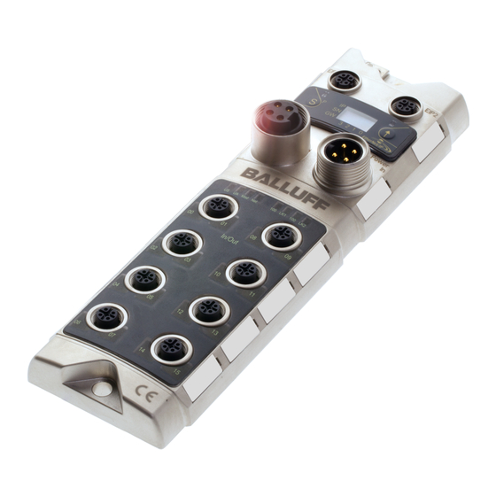
Port 4 EtherNet/IP™ port 2 Port 3 Display Port 2 Status LED: Communication / Module Port 1 Port 5 Power Supply Port Pin/Port LED : Signal status Label Port 6 EtherNet/IP™ port 1 Port 7 Grounding connection Port 8 www.balluff.com... -
Page 7: Mechanical Connection
Balluff Network Interface EtherNet/IP™ Getting Started 3.2. Mechanical The module is attached using 2 M6 screws and 2 washers. connection Isolation pad as accessory available 3.3. Electrical connection Power Supply Function Description +24 V Output Power +24 V Input Power... -
Page 8: I/O-Port
For the digital sensor inputs follow the input guideline per EN61131-2, type 2. Note! Each output serves a maximum current of 1,6 amperes. Total current of the module has to be lower than 9 amperes. Note! Unused I/O port socket must be fitted with cover caps to ensure IP67 protection rating. www.balluff.com... -
Page 9: Technical Data
Balluff Network Interface EtherNet/IP™ Technical data 4.1. Dimensions 4.2. Mechanical data Housing material Die case zinc, matt nickel plated Enclosure rating per IEC 60529 IP 67 (only when plugged-in and threaded-in) 7/8” 4-pin male / female Supply voltage Input ports / Output ports... -
Page 10: Ethernet
State of the Input or Output Pin is 1 Short-circuit single LED: Short-circuit on dedicated Pin (only if this pin is used as an output) both LEDs: Short-circuit between Pin 1 and 3 or Short-circuit on both output pins www.balluff.com... -
Page 11: Process Data
Balluff Network Interface EtherNet/IP™ Process Data 5.1. Data Please enter the following values to your Control System. They describe the datasizes for Configuration input, output and config data. BNI EIP-302-105- Z015 Instance ID Data length INPUT OUTPUT 5.2. Process Data There are 8 bytes of Input data. -
Page 12: Data Configuration
Description Output data Output on port 0 pin 4 Restart Restart output here after a detected short-circuit Reserved Display Control DL: Display lock / PLC lock GO: Green LED on Display on RO: Red LED on Display on www.balluff.com... -
Page 13: Data Configuration
Balluff Network Interface EtherNet/IP™ Process Data 5.7. Data Please enter the following values to your Control System. They describe the datasizes for Configuration input, output and config data. BNI EIP-104-105- Z015 Instance ID Data length INPUT OUTPUT 5.8. Process Data There are 6 bytes of Input data. -
Page 14: Display
6 LED 6.4. Display Cursor for selecting address type information Cursor zur Auswahl der Adressausprägung Cursor for selecting octet IP: IP address 3: fourth octet SN: Subnet address 2: third octet GW: Gateway address 1: second octet 0: first octet www.balluff.com... -
Page 15: Design And Symbols
Balluff Network Interface EtherNet/IP™ Display 6.5. Design and There are some symbols used in the following flow-charts to describe the display- Symbols functionality: actual state change-over condition: short-time keypress on set key condition: long-time keypress on setkey (min. 3 seconds) ... -
Page 16: Ip Setup
The entered value can immediately seen on the ip overview screen. • Manual changes of ip, subnet or gateway results in automatic change to “static” in IP Setup. Note: To work with the new configuration the module needs a power-down reset. www.balluff.com... -
Page 17: Module Information
Balluff Network Interface EtherNet/IP™ Display 6.10. Module information Version MAC-ID … EIP-302- SW: x.x XX : XX : XX : 100-Z016 HW: x.x XX : XX : XX • By short-time keypress on arrow key you can scroll through module information menu. -
Page 18: Webserver
First make sure that a correct integration into your network has been done. To get a connection to the webserver enter the IP address of the module to your browser address bar. A welcome page with a list of all Balluff Ethernet Network-interfaces is shown. Please use Internet Explorer 7 or higher. -
Page 19: Appendix
Ground strap • Screw M4x6 • 20 labels 8.2. Order code BNI EIP-xxx-105-Z015 Balluff Network Interface Ethernet IP Functions 302 = IP 67 Input/Output-Module 202 = IP 67 Output-Module 104 = IP 67 Input-Module Variants 105 = Display version, 2-port switch... - Page 20 Balluff GmbH Schurwaldstrasse 9 73765 Neuhausen a.d.F. Germany Tel. +49 7158 173-0 Fax +49 7158 5010 www.balluff.com balluff@balluff.de...
Need help?
Do you have a question about the BNI EIP-104-105-Z015 and is the answer not in the manual?
Questions and answers