
Related Manuals for Balluff BNI ECT-507-005-Z040


Summary of Contents for Balluff BNI ECT-507-005-Z040
- Page 1 BNI ECT-507-005-Z040 BNI ECT-527-005-Z040 IP67 Module 4 IO-Link Class A and 4 in- and outputs 4 IO-Link Class B and 4 inputs User's Guide...
-
Page 2: Table Of Contents
Configuring IO-Link module 5.4. Bit mapping and function Inputs pin 4 Inputs pin 2 Outputs pin 4 Outputs pin 2 IO–Link modules SIO module Short-circuit Pin 4 / Pin 2 Restart Pin 4 / Pin 2 (Class A only) www.balluff.com... -
Page 3: Inputs Pin
Balluff Network Interface EtherCAT™, BNI ECT-5x7-005-Z040 IO-Link state Sensor short circuit 5.5. Startup Configuration of the modules Validation Parameter server Upload flag on the IO-Link device Safe state 5.6. IO-Link parameterization Control Status Example - CoE setting Example - Read... -
Page 4: General
Cross-references indicate where additional information on the topic is located. 1.3. Symbols Note This symbol indicates general notes. Caution This symbol indicates a security notice which must be observed. 1.4. Abbreviations Balluff Network Interface Standard input port EtherCAT™ Electromagnetic Compatibility Function ground Standard output port Ethernet over EtherCAT™... -
Page 5: Safety
Before working on the device, switch off its power supply. Note In the interest of continuous improvement of the product, Balluff GmbH reserves the right to change the technical data of the product and the content of these instructions at any time without notice. www.balluff.com... -
Page 6: First Steps
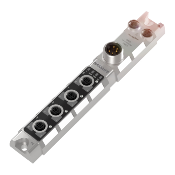
First Steps 3.1. Module Overview Figure – Overview BNI ECT-5xx-005-Z040 Mounting hole Port 1 EtherCAT™-Port 1 IN Port 0 Labels Power IN Status LED: communication / module EtherCAT™-Port 2 OUT Pin/port LED: signal status Ground connection Port 3 Port 2 www.balluff.com... -
Page 7: Mechanical Connection
Balluff Network Interface EtherCAT™, BNI ECT-5x7-005-Z040 First Steps 3.2. Mechanical The module is secured by means of two M6 screws and two washers. Connection Insulation support is available separately. 3.3. Electrical Connection Power supply Function Description GND actuator supply GND module / sensor supply... -
Page 8: Io-Link Port
The digital inputs conform to the input characteristics in EN61131-2, Type 3. Note The IO-Link output is powered from the sensor supply. Note Unused I/O ports must be provided with cover caps to comply with degree of protection IP67. www.balluff.com... -
Page 9: Technical Data
Balluff Network Interface EtherCAT™, BNI ECT-5x7-005-Z040 Technical Data 4.1. Dimensions 4.2. Mechanical Data Housing material Zinc die casting, matte nickel-plated Enclosure rating per IEC 60529 IP 67 (only in plugged-in and screwed-down state) Dimensions (W x L x H in mm) 37 x 224 x 32.6... -
Page 10: Function Indicators
No IO-Link – connection Green, rapid flashing IO-Link pre-operate during data storage Validation failed / incorrect configuration of the IO-Link data length Red, rapid flashing Data storage failed / incorrect device for data storage IO-Link short circuit pin 4 to pin 3 www.balluff.com... -
Page 11: Integration
Balluff Network Interface EtherCAT™, BNI ECT-5x7-005-Z040 Integration 5.1. EtherCAT™ The communication between the BNI ECT-5x7-005-Z040 and the controlling system is done via EtherCAT™. The system consists of the following components: Bus master Bus module/slaves (in this case the bus module BNI ECT-5x7-005-Z040) -
Page 12: Integration Into Project Planning Software
Integration 5.3. Integration into For example, the connection of the BNI ECT-507-005-Z040 to a Beckhoff TwinCAT Project Planning controller is shown with the TwinCAT System Manager. The exact procedure depends on Software the project planning software used. Installing ESI files The device description has the following name: Balluff BNI ECT-5x7-005-Z040_xxxxxx.xml... -
Page 13: Manually Attach Device
Balluff Network Interface EtherCAT™, BNI ECT-5x7-005-Z040 Integration Manually attach Before connecting devices to the EtherCAT™ network the EtherCAT™ system device must be in a safe, power-off state. Turn on power and start the TwinCAT System Manager in Config mode. -
Page 14: Required Setting On The Device
TwinCAT and already has the default configuration. BNI ECT-5x7-005-Z040 supports EoE (Ethernet over EtherCAT™). To configure TwinCAT accordingly, select "Advanced Settings" on the EtherCAT™ tab. A valid DNS name must be entered first and then a valid IP address. www.balluff.com... -
Page 15: Station Alias
Balluff Network Interface EtherCAT™, BNI ECT-5x7-005-Z040 Integration Station alias The station alias can be entered under the following menu: EtherCAT™ tab, select "Advanced settings". Open ESC Access, open E²PROM and click on Configured Station. The new value is valid only after a reset. -
Page 16: Configuring Io-Link Module
Output Pin 2 (Class A only) Restart Pin 2 (Class A only) Restart Pin 4 (Class A only) The slots for future expansions are not used. A number of process data (buffer size) can be assigned to the other slots. www.balluff.com... -
Page 17: Bit Mapping And Function
Balluff Network Interface EtherCAT™, BNI ECT-5x7-005-Z040 Integration 5.4. Bit mapping and Bit mapping and function of the configurable modules function Inputs pin 4 Signal from configured inputs or outputs are depicted in the modules Inputs pin 2 STD_IN_1bit (input pin 4), input pin 2 as well as Outputs pin 4 STD_OUT_1bit (output pin 4) and output pin 2. -
Page 18: Io-Link State
0x9_ = invalid PD out length 0xA_ = no device detected Sensor short circuit Feedback as to the port at which a sensor supply short circuit is pending. Bit 7 Bit 6 Bit 5 Bit 4 Bit 3 Bit 2 Bit 1 Bit 0 www.balluff.com... -
Page 19: Startup
Balluff Network Interface EtherCAT™, BNI ECT-5x7-005-Z040 Integration 5.5. Startup In the startup, the IO-Link ports and outputs can be pre-configured. The entries are transferred when the configuration is overwritten Configuration of the modules www.balluff.com... -
Page 20: Validation
When the connected IO-Link device is started, a validation takes place. Thus, only an IO-Link device of the same type can be used for the data management. To use an IO-Link device of a different type, the contents of the parameter server must be deleted. www.balluff.com... -
Page 21: Upload Flag On The Io-Link Device
Balluff Network Interface EtherCAT™, BNI ECT-5x7-005-Z040 Integration Upload flag on To enable the upload flag of an IO-Link device, the IO-Link the value 0x05 must be entered in the index 0x02, subindex 0. device (Parameterization, see IO-Link Service Data on the next page) -
Page 22: Io-Link Parameterization
0x04: Error 0xFF: Failure Example - CoE A short example shows how Index 0x40 for a SmartLight (Mode) is changed. setting Select mode CoE - Open Online Set CoE a. Under Advanced ….set to Online b. Enable Auto Update www.balluff.com... -
Page 23: Example - Read
Balluff Network Interface EtherCAT™, BNI ECT-5x7-005-Z040 Integration Example - Read In Port select 4030:0 (here Channel 4) First read the index, i.e. double-click 4030:03 and specify the respective index - 0x0040 (64) Now in Control write command 0x03 Then the contents of the index is read and displayed in Data. -
Page 24: Object List
0: no control action 3: read 2: write 0x02 Status UINT8 0: no activity 1: busy 2: success 4: error 0xFF: failure 0x03 Index UINT16 0x04 Subindex UINT8 0x05 Length UINT8 0x06 Data UINT232 n = 0..3 0x07 Error Code UINT16 www.balluff.com... -
Page 25: Io-Link Configuration Data Ch. X (0X8000 - 0X8Fff)
Balluff Network Interface EtherCAT™, BNI ECT-5x7-005-Z040 Object list 6.8. IO-Link Index Sub- Name DataType Access Description/ Configuration index Value Data Ch. x 0x80n0 0x04 Device ID UINT32 (0x8000 – 0x05 Vendor ID UINT32 0x8FFF) 0x06 Product ID UINT32 0x08 Serial Number... -
Page 26: Configuration Without Esi
IOL_I_4byte 0x83 0x00 IOL_I_6byte 0x85 0x00 IOL_I_8byte 0x87 0x00 IOL_I_10byte 0x89 0x00 IOL_I_16byte 0x8F 0x00 IOL_I_24byte 0x97 0x00 IOL_I_32byte 0x9F 0x00 IOL_I_1byte/O_1bytes 0x08 0x08 IOL_I_2byte/O_2bytes 0x16 0x16 IOL_I_2byte/O_4bytes 0x16 0x83 IOL_I_4byte/O_4bytes 0x83 0x83 IOL_I_4byte/O_2bytes 0x83 0x16 IOL_I_2byte/O_8bytes 0x16 0x87 www.balluff.com... -
Page 27: Web Server
Balluff Network Interface EtherCAT™, BNI ECT-5x7-005-Z040 Web Server 7.1. General The BNI fieldbus module provides an integrated web server for retrieving detailed device information and for configuring the device. To use the web interface you must first ensure that the module has been correctly integrated into your network. -
Page 28: Navigation / Help
Directly below the selected navigation icon a short text appears which shows the current dialog selection. The footer of the Help dialog contains the copyright statement and the version of the web interface. The "BALLUFF" logo at upper right links to the international Balluff homepage. -
Page 29: Login/Logout
Balluff Network Interface EtherCAT™, BNI ECT-5x7-005-Z040 Web Server 7.3. Login/Logout To be able to make configuration setting on the fieldbus module through the web interface, you must first be logged in, since otherwise dialogs and functions are not accessible, as indicated by grayed out buttons inside the dialogs. -
Page 30: Home" Dialog
If an IO-Link device is connected to one of the configured IO-Link terminals, some of the device data will be displayed in addition to the module data in the form of a link. After selecting one of these links the corresponding device dialog is opened. www.balluff.com... - Page 31 Balluff Network Interface EtherCAT™, BNI ECT-5x7-005-Z040 Web Server Note You can monitor only the process data and the current status of the module. It is not possible to configure a module or set the output data. In this case, you have to use the control unit together with the corresponding operating software.
-
Page 32: Ports" Dialog
Under "Parameter server content" you can view the content of the parameter server if parameter data is stored on the parameter server. Note You can monitor the process data and the current status of the module. Configuration is only possible if you are logged in and not connected to the controller (PLC). www.balluff.com... -
Page 33: Configuration" Dialog
Balluff Network Interface EtherCAT™, BNI ECT-5x7-005-Z040 Web Server 7.6. "Configuration" The configuration page permits configuration of the module. You can change the displayed dialog module information texts and module parameters. The "Set Ports" action is not permanently stored in the device and is lost after the next reboot. -
Page 34: Log" Dialog
These may include also configuration actions over the web interface and other configuration interfaces which are also recorded. These messages are classified as "Notice“. Pressing "Set Module Time“ sends the current browser time to the fieldbus module. Pressing "Update Log" updates the display. www.balluff.com... -
Page 35: Appendix
• Ground strap • M4x6 screw • 20 informational signs 8.2. Order number BNI ECT-5x7-005-Z040 Balluff Network Interface EtherCAT™ Functions 507 = 4 IO-Link Ports Class A 527 = 4 IO-Link Ports Class B Variants 005 = 2-Port-Switch Mechanical version... -
Page 36: Notes
Notes www.balluff.com... -
Page 37: Www.balluff.com
Balluff GmbH Schurwaldstrasse 9 73765 Neuhausen a.d.F. Germany Phone +49 7158 173-0 Fax +49 7158 5010 www.balluff.com balluff@balluff.de...
Need help?
Do you have a question about the BNI ECT-507-005-Z040 and is the answer not in the manual?
Questions and answers