Table of Contents
Advertisement
Advertisement
Table of Contents

Subscribe to Our Youtube Channel
Related Manuals for Balluff BNI PNT-502-102-Z015


Summary of Contents for Balluff BNI PNT-502-102-Z015
- Page 1 BNI PNT-502-102-Z015 IP67 Module User´s Guide...
-
Page 2: Table Of Contents
Hardware configuration IO-Link configuration Device name, Profinet address Establishing device relationship Assigning device name Concluding the configuration 5.2. Functions in module properties Module settings Port functions Safe state 5.3. Bit mapping and function Inputs pin 4 Inputs pin 2 www.balluff.com... -
Page 3: Outputs Pin
Block Length Block Version High Block Version Low Alarm Type Slot Subslot Module ID Submodule ID 8.3. AlarmSpecifier Sequence Number Channel Diagnostic Manufacturer-Specific Diagnosis Submodules Diagnostic State ARDiagnosis State User Structure ID 8.4. Channel Number 8.5. Channel Properties Type www.balluff.com... - Page 4 Accumulative Maintenance Specifier Direction 8.6. Channel Error Type Configuration of IO-Link devices General Function block Reading Writing Appendix 10.1. Scope of delivery 10.2. Order number 10.3. Order information Notes www.balluff.com...
-
Page 5: General
Symbols Note This symbol indicates general notes. Attention! This symbol indicates a safety instruction that must be followed without exception. 1.4. Abbreviations Balluff Network Interface Electromagnetic Compatibility Functional ground Standard input port Standard output port ProfiNet™ Actuator supply undervoltage Sensor supply undervoltage 1.5. -
Page 6: Safety
Attention! voltage Disconnect all power before servicing equipment. Note In the interest of product improvement, the Balluff GmbH reserves the right to change the specifications of the product and the contents of this manual at any time without notice. www.balluff.com... -
Page 7: Getting Started
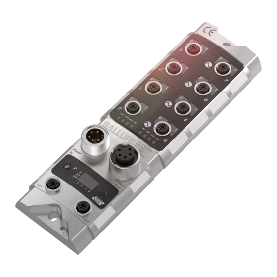
Getting Started 3.1. Module overview Figure 1 – Overview of BNI PNT-502-102-Z015 Port 3 Display Port 2 Power OUT Port 1 Status LEDs Pin/Port LEDs Port 4 Port 0 Port 5 Power IN Port 6 Label Port 7 PROFINET ™ port 1... -
Page 8: Mechanical Connection
Balluff Network Interface ProfiNet™ Getting Started 3.2. Mechanical The module is secured by means of two M6 screws and two washers. connection Insulation support is available separately. 3.3. Electrical connection Power supply Power supply "INPUT" (7/8", connector) Function Description Bus/sensor and actuator power... -
Page 9: Profinet Interface
Unused I/O ports must be provided with cover caps in order to ensure enclosure rating IP67. IO-Link port M12, A-coded, female Function +24 V, 1.6 A Input/output 2A IO-Link / input / output 2A n.a. Port Port BNI PNT-502-102-Z015 IN / OUT IN / OUT / IO-Link www.balluff.com... -
Page 10: Technical Data
Balluff Network Interface ProfiNet™ Technical data 4.1. Dimensions 4.2. Mechanical data Housing material Die-cast zinc, matte nickel-plated Housing protection type in IP 67 (only in plugged-in and screwed-down state) accordance with IEC 60529 Supply voltage 7/8" 5-pin, connector / female... -
Page 11: Profinet
Red, flashing Service DCP signal started via bus No error Low speed of physical link; or no physical link Red, flashing No data exchange or no configuration Transmission rate: 10 Mbit/s Yellow Transmission rate: 100 Mbit/s Green Data transfer www.balluff.com... -
Page 12: Port
Balluff Network Interface ProfiNet™ Technical data Port Standard port Status Function Status of input or output pin is 0 Yellow Status of input or output pin is 1 Both LEDs flashing red Short circuit at sensor supply between pin 1 and pin 3... -
Page 13: Integration
The device data required for project planning is saved in GSDML files (Generic Station Description Markup Language). The GSDML files are available in two languages as an Internet download (www.balluff.com). The data modules of an IO-Link module are depicted in the project planning software according to the slot. -
Page 14: Configuration Of The Header Module
Balluff Network Interface ProfiNet™ Integration Configuration of Double-click on the header module to open its properties. the header Click on the "Parameter" tab to open a menu selection for defining the module port functions and diagnostic functions. Note IO-Link configuration: For modules with an firmware version 2.3 or higher, the configuration of pin 4 as... -
Page 15: Hardware Configuration
For the SIO function, integrate the "IO-Link input with SIO mode" module. With the remaining modules, the various functions are mapped into the process data areas. A description of the individual modules is provided in chapter "Bitmapping and function". www.balluff.com... -
Page 16: Io-Link Configuration
Balluff Network Interface ProfiNet™ Integration IO-Link Double-click on the IO-Link module to change the IO-Link parameters of the configuration respective port pins. A description of the individual modules is provided in chapter "Function in the module properties." www.balluff.com... -
Page 17: Device Name, Profinet Address
Integration Device name, Double-click on the module in the Profinet line to view the communication Profinet address parameters of the module. The device name and the Profinet address (IP) are configured here. www.balluff.com... -
Page 18: Establishing Device Relationship
Balluff Network Interface ProfiNet™ Integration Establishing Navigate through "Target system" -> "Ethernet" -> "Assign device name" to start the tool for device assigning the module a device name. relationship Assigning device Select the desired name and use "Assign name" to assign the marked device that you name found. -
Page 19: Concluding The Configuration
IO-Link is configured in the header module, the slot module is, however, missing or is connected at the wrong location. The IO-Link module is at the correct location, pin 4 was, however, not configured to IO-Link for the IO-Link port via the header module. www.balluff.com... -
Page 20: Functions In Module Properties
Balluff Network Interface ProfiNet™ Integration 5.2. Functions in Description of the functions in module properties module properties Module settings Global diagnostics: This function can be used to permit / suppress all diagnostics messages of the module. (optical diagnostics signals and diagnostics in configured diagnostics modules... -
Page 21: Bit Mapping And Function
If this function is configured, no automatic restart is performed after an actuator pin 2 short-circuit, but rather the port must be activated by inserting the corresponding bit. Bit 7 Bit 6 Bit 5 Bit 4 Bit 3 Bit 2 Bit 1 Bit 0 www.balluff.com... -
Page 22: Switching Io-Link Diagnostics On / Off
Balluff Network Interface ProfiNet™ Integration Switching IO-Link If this function is configured, the IO-Link diagnostics is deactivated diagnostics on / off for all ports and can be reactivated for the desired ports. Bit 7 Bit 6 Bit 5 Bit 4... -
Page 23: Io-Link Functions
Identity: Manufacturer ID and device ID as well as the serial number are compared to the module data. The IO-Link communication is only started if there is a match. Manufacturer ID and device ID are entered in decimal format, the serial number is entered in ASCII code. www.balluff.com... -
Page 24: Parameter Server
Balluff Network Interface ProfiNet™ Integration Parameter server Switched on: data management functions enabled, parameter data and identification data of the IO-Link device are stored permanently. Switched off: data management functions disabled, stored parameter data and identification data of the IO-Link device remain stored. -
Page 25: Display
6.1. General The display element of the BNI PNT-502-102-Z015 consists of two LEDs, two buttons and a LCD display. A backlight is built in to increase readability in low-light environments and is activated if you start going through the menu. -
Page 26: Design And Symbols
Balluff Network Interface ProfiNet™ Display 6.4. Design and There are some symbols used in the following flow-charts to describe the display- symbols functionality: Actual state Change-over Condition: short-time keypress on Set-Key Condition: long-time keypress on Set-Key (min. 3 seconds) ... -
Page 27: Factory Reset
MAC-ID: PNT-502- HW: 1 00:19:31: 102-Z015 SW: 1.1 30:44:0A • Go through the Module Info menu with short-time keypress on Arrow-Key. • You can select between the device name, the hard and software version and the MAC-ID. www.balluff.com... -
Page 28: Webserver
Balluff Network Interface ProfiNet™ Webserver 7.1. General The BNI fieldbus module contains an integrated web server for retrieving detailed device information and for configuring the device. To use the web interface you must first ensure that the module has been correctly integrated into your network. -
Page 29: Navigation / Info
The navigation bar is located in the upper area of the window, which allows you to switch between the various dialogs of the web interface. To do this click on the corresponding icon. When the "Info" tab is selected the following overview appears: The "BALLUFF" logo at upper right links to the international Balluff homepage. www.balluff.com... -
Page 30: Login/Logout
Balluff Network Interface ProfiNet™ Webserver 7.3. Login/Logout To make configuration settings on the fieldbus module using the web interface, you must first log in. Functionalities which cannot be used without logging in are indicated by the grayed out buttons. The default password is: "BNIPNT“... -
Page 31: Home" Dialog
If an IO-Link device is connected to one of the configured IO-Link terminals, some of the device data will be displayed in addition to the module data in the form of a link. After selecting one of these links the corresponding device dialog is opened. www.balluff.com... - Page 32 Balluff Network Interface ProfiNet™ Webserver PNT: EIP: www.balluff.com...
-
Page 33: Ports" Dialog
Under "Events" you can see whether a diagnostic event from the IO-Link device exists. Under "Parameter Server Content" you can view the content of the parameter server if parameter data is stored on the parameter server. "Ports" dialog with direct parameter access www.balluff.com... -
Page 34: Appropriate Iodd Uploaded
Balluff Network Interface ProfiNet™ Webserver Appropriate IODD If an IODD appropriate to the IO-Link device connected to the currently selected port has uploaded been uploaded (see "Dialog "IODD"), the normal dialog for "Process Data" and "Parameters" is not displayed, but rather an expanded dialog. - Page 35 If the IODD of the IO-Link device on the currently selected port has parameters, these are shown in table format (see following screenshot). In this example the parameters for the Balluff Smart Light are shown. The Smart Light is a signal light which can be used in three different modes. These modes can be set using an IO-Link parameter.
-
Page 36: Iodd" Dialog
Balluff Network Interface ProfiNet™ Webserver 7.6. "IODD" dialog Using this dialog you can transfer IODDs (device description files for IO-Link devices) and the associated device images to the fieldbus module, so that a detailed representation of the connected IO-Link devices in the "Ports" dialog is possible. -
Page 37: Config" Dialog
The configuration page enables configuration of the module. You can change both the module information texts and the port configuration. The "Set Ports" action is not permanently stored in the device and is lost after the next reboot or reset. PNT / ECT: www.balluff.com... - Page 38 Balluff Network Interface ProfiNet™ Webserver EIP: The parameter set “Module Configuration” on the left side is used by clicking "Save Configuration" and permanently stored in the device. The "Reboot" button reboots the device as if the power to the module had been turned off and on again.
-
Page 39: Log" Dialog
If you have a detailed question about a specific situation, send us a screenshot of this Web site or print the site as a PDF. Logging shows events which have occurred in chronological order. This provides a tool for detailed troubleshooting in equipment. www.balluff.com... - Page 40 Balluff Network Interface ProfiNet™ Webserver Events are classified using the "Severity“ column: Internal Error (Emergency, Alert, Critical) The fieldbus module has detected a fault in itself (hardware or software) which should not occur during normal operation. If this happens, the module must be serviced or replaced.
-
Page 41: Diagnostics
Block Header, Alarm Specifier, Channel Properties Byte Value Meaning Block Block Type Block Length Block Version High Block Version Low Alarm type Block Header Slot number Subslot number Module ID Submodule ID AlarmSpecifier User Structure ID AlarmSpecifier Channel number ChannelProperties ChannelProperties ChannelErrorType www.balluff.com... -
Page 42: Block Header
(The module ID is saved in the GSDML) Possible values Meaning 0x00000017 BNI PNT-502-102-Z015 (header module) Submodule ID 4 bytes of data that describe which submodule is used with the respective module. (The submodule ID is saved in the GSDML.) -
Page 43: Alarmspecifier
State Possible values Meaning 0x00 No further diagnosis of module is present 0x01 At least one further diagnosis of the module is present User Structure ID 2 bytes, describes the type of diagnosis Possible values Meaning 0x8000 Channel-related diagnosis www.balluff.com... -
Page 44: Channel Number
Balluff Network Interface ProfiNet™ Diagnostics 8.4. Channel Number 2 bytes of data that describe where the error on the module has occurred. Slot 1: Configuration as standard I/O ports Value Position 0x0000 Port 0 pin 4 0x0001 Port 1 pin 4... -
Page 45: Channel Properties
Diagnosis appeared 0x02 Diagnosis left 0x03 Diagnosis left, but another is still active Bit 11-12 Direction Possible values Meaning 0x00 Manufacturer-specific 0x01 Channel used as input 0x02 Channel used as output 0x03 Channel used as input and output Bit 13-15 www.balluff.com... -
Page 46: Channel Error Type
Balluff Network Interface ProfiNet™ Diagnostics 8.6. Channel Error Error code in hex Description Type 0x0000 Unknown error 0x0001 Short circuit 0x0002 Undervoltage 0x0003 Overvoltage 0x0004 Overload 0x0005 Temperature limit exceeded 0x0006 Cable break 0x0007 Upper threshold exceeded 0x0008 Lower threshold undershot... -
Page 47: Configuration Of Io-Link Devices
Therefore the following settings are used: Diagnosis address The diagnosis address from slot 1 is used The sample project with the IOL_Call function module from Siemens AG can be downloaded on the Balluff homepage. The telegram has the following structure: Area Size in bytes... -
Page 48: Appendix
Balluff Network Interface ProfiNet™ Appendix 10.1. Scope of The BNI PNT comprises the following elements: • delivery IO-Link block • 4x M12 dummy plugs • Ground strap • M4x6 screw • 20 information signs 10.2. Order number BNI PNT-502-102-Z015 Balluff network interface... -
Page 49: Notes
Notes www.balluff.com... - Page 50 Balluff Network Interface ProfiNet™ www.balluff.com Balluff GmbH Schurwaldstrasse 9 73765 Neuhausen a.d.F. Germany Tel. +49 7158 173-0 Fax +49 7158 5010 www.balluff.com balluff@balluff.de...
Need help?
Do you have a question about the BNI PNT-502-102-Z015 and is the answer not in the manual?
Questions and answers