
Subscribe to Our Youtube Channel
Related Manuals for Balluff BNI EIP-306-100-Z010


Summary of Contents for Balluff BNI EIP-306-100-Z010
- Page 1 BNI EIP-306-000-Z010 BNI EIP-306-100-Z010 IP67 Module,16 Inputs and 16 Outputs BNI EIP-308-100-Z010 IP67 Module, 32 In-/Outputs User’s Guide...
-
Page 2: Table Of Contents
6.4. Process Data Outputs BNI EIP-308-…. Display 7.1. General Address Defaults Controls and Visualization Display Information Symbols 7.2. Startup 7.3. Main Menu 7.4. Octet scrolling 7.5. IP Configuration 7.6. General Information Webserver 8.1. General 8.2. Home 8.3. Diagnostic Process www.balluff.com... - Page 3 Balluff Network Interface EtherNet/IP™, BNI EIP-302-105-Z015 8.4. Diagnostic Module 8.5. Configurations Appendix 9.1. Product Name 9.2. Order Code 9.3. Included Material www.balluff.com...
-
Page 4: Notes
4 ”Technical Data”). Symbols Note tip This symbol indicates general notes. Note! This symbol indicates a security notice which most be observed. 1.4. Abbreviations Balluff Network Interface Standard input port EtherNet/IP™ Electromagnetic Compatibility Function ground Standard output port www.balluff.com... -
Page 5: Safety
Balluff Network Interface EtherNet/IP™ Safety 2.1. Intended use This guide describes The BNI EIP-… serves as a decentralized input and output module for connecting to an EtherNet/IP™ network. 2.2. General safety Installation and startup are to be performed only by trained specialists. Any damage notes resulting from unauthorized manipulation or improper use voids the manufacturer’s... -
Page 6: Getting Started
Port 02 / 03 Output Port 14 / 15 Output Port 00 / 01 Output Port 08 / 09 Input Power Supply Port Port 10 / 11 Input Label EtherNet/IP™ port Port 12 / 13 Input Port 14 / 15 Input Grounding connection www.balluff.com... -
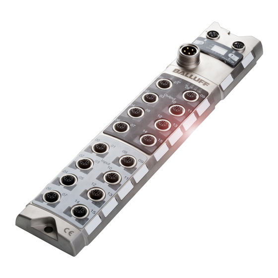
Page 7: Module Overview Display Bni Eip-306-100
Balluff Network Interface EtherNet/IP™ Getting Started 3.2. Module Overview Display BNI EIP-306-100.. BNI EIP-306-100-Z010 Mounting hole Port 06 / 07 Input IPAP, Programming Interface Port 04 / 05 Input Display Port 02 / 03 Input Status LED: Communication / Module... -
Page 8: Module Overview Bni Eip-308-100-Z010
Port 00 / 01 In-/ Output Port 24 / 25 In-/ Output Power Supply Port Port 26 / 27 In-/ Output Label EtherNet/IP™ port Port 28 / 29 In-/ Output Port 30 / 31 In-/ Output Grounding connection Port 22 / 23 In-/ Output www.balluff.com... -
Page 9: Mechanical Connection
Balluff Network Interface EtherNet/IP™ Getting Started 3.4. Mechanical The module is attached using 2 M6 screws and 2 washers. connection Isolation pad as accessory available 3.5. Electrical connection Power Supply Function Description +24 V Output Power +24 V Input Power... -
Page 10: I/O-Port
For the digital sensor inputs follow the input guideline per EN61131-2, type 2. Note! Each output serves a maximum current of 2 amperes. Total current of the module has to be lower than 9 amperes. Note! Unused I/O port socket must be fitted with cover caps to ensure IP67 protection rating. www.balluff.com... -
Page 11: Technical Data
Balluff Network Interface EtherNet/IP™ Technical data 4.1. Dimensions 4.2. Mechanical data Housing material Die case zinc, matt nickel plated Enclosure rating per IEC 60529 IP 67 (only when plugged-in and threaded-in) 7/8” 4-pin male Supply voltage Input ports / Output ports... -
Page 12: Ethernet
State of the Input or Output Pin is 1 Short-circuit single LED: Short-circuit on dedicated Pin (only if this pin is used as an output) both LEDs: Short-circuit between Pin 1 and 3 or Short-circuit on both output pins www.balluff.com... -
Page 13: Integration
Balluff Network Interface EtherNet/IP™ Integration 5.1. Integration into RSLogix (3) Start/Open RSLogix 5000 Project (4) Add EtherNet/IP Communication Module to the I/O Configuration (5) Right-Click I/O Configuration Folder and Choose “New Module www.balluff.com... - Page 14 Integration (6) Choose Communication Module from List (7) Click “OK” Configuration of the generic module for Balluff EtherNet/IP modules (8) Name of the module (9) Choose “Data-SINT” at „Comm Format (10) Enter the IP address for the Balluff module (11) Entert the „Assembly Instance“ and the size of the inputs, outputs and the configurations.
-
Page 15: Process Data
Balluff Network Interface EtherNet/IP™ Process Data 6.1. Process Data Input Description BNI EIP-306- x00-… Input data Short circuit status Output Handshake HS15 HS14 HS13 HS12 HS11 HS10 OL23 OL22 OL21 OL20 OL19 OL18 OL17 OL16 Overload status OL31 OL30 OL29... -
Page 16: Process Data Inputs Bni Eip-308
R152 R154 R142 R144 R132 R134 R122 R124 IPAP Control RO: Red LED on RF: Red LED flashing YO: Yellow LED on YF: Yellow LED flashing Display Control RO: Red LED on GO: Green LED on PL: PLC lock active www.balluff.com... -
Page 17: Display
Balluff Network Interface EtherNet/IP™ Display With the implemented display, the address is set directly on the BNI EIP… devices. 7.1. General The following address types are implemented: IP address Subnet mask Gateway address. Each address type consists of 4 octets. -
Page 18: Symbols
Scrolling in main menu with short-time keypress on set-key Switch to next octet of the selected address type by short keypress on arrow-key 7.4. Octet scrolling 1st octet 2nd octet 4th octet 3rd octet Octet scrolling is similar for all Address types. www.balluff.com... -
Page 19: Ip Configuration
Balluff Network Interface EtherNet/IP™ Display 7.5. IP Configuration editing mode Long-time key press on set key starts editing mode. Configuration of the selected value by short-time key press on arrow-key After configuration store the new value by long-time keypress on set-key. -
Page 20: Webserver
First make sure that a correct integration into your network has been done. To get a connection to the web server enter the IP address of the module to your browser address bar. A welcome page with a list of all Balluff Ethernet Network-interfaces is shown. Please use Internet Explorer 7 or higher. -
Page 21: Appendix
Balluff Network Interface EtherNet/IP™ Appendix 9.1. Product Name BNI EIP-308-100-Z010 Balluff Network Interface Ethernet IP Functions 306 = IP67 I/O-Module, 16 Inputs and 16 Outputs 308 = IP67 I/O-Module, 32 In- / Outputs Variants 000 = without Display (Standard) 100 = Display version... -
Page 22: Www.balluff.com
Balluff GmbH Schurwaldstrasse 9 73765 Neuhausen a.d.F. Germany Tel. +49 7158 173-0 Fax +49 7158 5010 www.balluff.com balluff@balluff.de...
Need help?
Do you have a question about the BNI EIP-306-100-Z010 and is the answer not in the manual?
Questions and answers