Advertisement
Advertisement
Table of Contents

Subscribe to Our Youtube Channel
Related Manuals for Balluff MICROPULSE BTM-AR2-001


Summary of Contents for Balluff MICROPULSE BTM-AR2-001
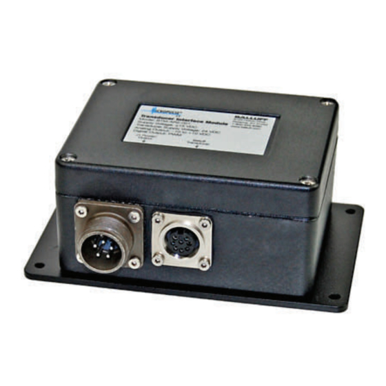
- Page 1 BTM-AR2-001 Transducer Interface Module...
-
Page 2: Table Of Contents
Setup and Programming Functional Description The BTM-AR2-001 module provides dual position outputs when used in conjunction with Balluff Micropulse linear position transducers with a digital Start/Stop output. The BTM-AR2-001 provides both analog -10 to +10Vdc and pulse width modulated (PWM) position output signals. The BTM-AR2-001 module is user- programmable to meet a wide variety of application requirements. -
Page 3: Specifications
Input Module Output Selectable Active High/Active Low PWM Output to Control * Start/Stop Output from Transducer (Active High Output Shown) to interface / Trailing Edge Active Wiring J1 Power/Output Balluff Transducer Front Pin View Front Pin View www.balluff.com • 1-800-543-8390... -
Page 4: Dimensions
Installation Using Optional Mounting Plate Note: The included mounting plate adapter can be used to adapt the BTM-AR2-001 Interface Module to non- standard mounting surfaces. If the mounting plate adapter is not required, it may be discarded. Optional Mounting Plate (included) www.balluff.com • 1-800-543-8390... -
Page 5: Setup And Programming
Internal Layout / User Controls Information Card Green Program LED Red Error LED Up Button LCD Display Down Button SEL Button PGM Button J1 Power/ Output Con- nector Balluff Transducer www.balluff.com • 1-800-543-8390... - Page 6 (HEX), press the <UP> key for System Units. For the LCD to display raw posi- tion in Decimal, press the <DOWN> key for Normal. Press the <PGM> key to exit Configure Mode, and return to Run Mode. www.balluff.com • 1-800-543-8390...
- Page 7 1mSecs. Press <PGM> to continue to the next parameter. Adjust Gradient - Enter the gradient of the transducer. The gradient value is found on the Balluff transducer label in “µs/in” (e.g. grad=8.8843µs/in). Initially the gradient value is set to 9.0000 µs/in with the last digit blinking. Press the <UP>...
- Page 8 Note - This step is not needed if only the analog output is being used. 4. When the PWM Offset is properly set at the NULL point, press <PGM> to exit the Online Adjust Mode and return to Run Mode. www.balluff.com • 1-800-543-8390...
- Page 9 Mississauga, Ontario L5N 8G4 Phone: (905) 816-1494 Toll-free: 1-800-927-9654 Fax: (905) 816-1411 E-mail: balluff.canada@balluff.ca Mexico Balluff de Mexico S.A.de C.V Prol. Av. Luis M. Vega #109 Col. Ampliación Cimatario Queretaro, QRO 76030 Phone: (++52 442) 212-4882, 224-3583, 224-3171 Fax: (++52 442) 214-0536 E-mail: balluff.mexico@balluff.com...
Need help?
Do you have a question about the MICROPULSE BTM-AR2-001 and is the answer not in the manual?
Questions and answers