
Related Manuals for Balluff BNI EIP-508-105-Z015


Summary of Contents for Balluff BNI EIP-508-105-Z015
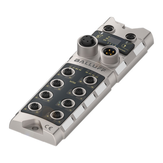
- Page 1 Machine Automation Controller NJ/NX-series EtherNet/IP Connection Guide Balluff GmbH Network Module (BNI EIP-50[]-105-Z015) P504-E1-01...
- Page 2 About Intellectual Property Rights and Trademarks Microsoft product screen shots reprinted with permission from Microsoft Corporation. Windows is a registered trademark of Microsoft Corporation in the USA and other countries. ODVA and EtherNet/IP are trademarks of ODVA. EtherCAT® is registered trademark and patented technology, licensed by Beckhoff Automation GmbH, Germany.
-
Page 3: Table Of Contents
6.2. Global Variables ..................10 6.3. Tag Sets ....................15 EtherNet/IP Connection Procedure ............16 7.1. Work Flow ..................... 16 7.2. Balluff Network Module Setup ............... 18 7.3. Controller Setup ..................23 7.4. Network Settings ................... 34 7.5. EtherNet/IP Communication Status Check ........... 51 Initialization Method .................. -
Page 4: Related Manuals
Safety Precautions and Precautions for Safe Use in the manuals for each device which is used in the system. The table below lists the manuals provided by Balluff GmbH (hereinafter referred to as "Balluff") and OMRON Corporation (hereinafter referred to as "OMRON"), which pertain to this guide. - Page 5 1.Related Manuals Manufacturer Cat. No. Model Manual name Balluff 933690-726 BNI EIP-50[]-105-Z015 BNI EIP-502-105-Z015 BNI EIP-508-105-Z015 EtherNet/IP IP67 Modules User’s Guide Balluff 893539 BNI EIP-50[]-105-Z015 BNI EIP-508-105-Z015 IP67 Modules 8IO-Link/In-/Outputs, 8 In-/Outputs User’s Guide...
-
Page 6: Terms And Definitions
2.Terms and Definitions 2. Terms and Definitions The terms and definitions used in this guide are given below. Term Explanation and Definition node A node refers to a relay point, a junction point or an end point on an EtherNet/IP network made up of devices having an EtherNet/IP port. A device with one EtherNet/IP port is recognized as one node and two EtherNet/IP ports as two nodes on an EtherNet/IP network. -
Page 7: Precautions
3.Precautions 3. Precautions (1) Understand the specifications of devices which are used in the system. Allow some margin for ratings and performance. Provide safety measures, such as installing a safety circuit, in order to ensure safety and minimize the risk of abnormal occurrence. (2) To ensure system safety, make sure to always read and follow the information provided in all Safety Precautions and Precautions for Safe Use in the manuals for each device which is used in the system. -
Page 8: Overview
4.Overview 4. Overview This guide describes procedures for connecting a Balluff Network Module (BNI EIP-50[]-105-Z015) (hereinafter referred to as the "Network Module") to an OMRON NJ/NX-series Machine Automation Controller (hereinafter referred to as the "Controller") via EtherNet/IP and for checking their communication status. -
Page 9: Applicable Devices And Device Configuration
NJ501-[]4[][] NJ501-[]3[][] NJ301-12[][] NJ301-11[][] NJ101-10[][] NJ101-90[][] Balluff Network Module BNI EIP-502-105-Z015 BNI EIP-508-105-Z015 Precautions for Correct Use In this guide, the devices with models and versions listed in 5.2. Device Configuration are used as examples of applicable devices to describe the procedures for connecting the devices and checking their connection. -
Page 10: Device Configuration
BNI EIP-508-105-Z015.eds 1.1(Major Revision: 4) Balluff Icon file BNI EIP-508-105-Z015.ico Module / sensor power supply (24 VDC) Actuator power supply (24 VDC) Precautions for Correct Use Prepare the EDS file listed above. To obtain the EDS file, contact Balluff GmbH. - Page 11 5.Applicable Devices and Device Configuration Precautions for Correct Use Note that the EDS file specified in this Clause 5.2. is not compatible with versions of the Network Module earlier than "H5_S[].[]". You need the EDS file with a different version that is compatible with earlier versions of the Network Module.
-
Page 12: Ethernet/Ip Settings
6.EtherNet/IP Settings 6. EtherNet/IP Settings This section describes the parameters, global variables and tag sets that are all defined in this guide. Hereinafter, the Network Module is referred to as the "Destination Device" in some descriptions. 6.1. Parameters The parameters set in this guide are shown below. 6.1.1. -
Page 13: Global Variables
6.EtherNet/IP Settings 6.2. Global Variables The Controller treats the data in tag data links as global variables. The following tables show the global variables and their related settings. ■Output area (Controller to Network Module) Name Data type Network publish Data size (byte) EIP002_Standard_IO_ports_OUT BYTE[6] Output... - Page 14 6.EtherNet/IP Settings ■Input area (Network Module to Controller) Name Data type Network publish Data size (byte) EIP002_Standard_IO_ports_IN BYTE[8] Input EIP002_IOLink_port0_1_IN BYTE[96] Input EIP002_IOLink_port2_3_IN BYTE[96] Input EIP002_IOLink_port4_5_IN BYTE[96] Input EIP002_IOLink_port6_7_IN BYTE[96] Input *Relationship between the global variables and the Network Module data Network Module Global variable Data...
- Page 15 6.EtherNet/IP Settings Network Module Global variable Data allocation EIP002_IOLink_port2_3_IN[0] to [47] IO-Link Same as for the data allocation "IO-Link port 0" port 2 EIP002_IOLink_port2_3_IN[48] to [95] IO-Link Same as for the data allocation "IO-Link port 1" port 3 EIP002_IOLink_port4_5_IN[0] to [47] IO-Link Same as for the data allocation "IO-Link port 0"...
- Page 16 6.EtherNet/IP Settings ■Process Data of Proximity Sensor (Data to be stored in the global variable EIP002_IOLink_port0_1_IN[0] listed in the table for the input area) (Data to be stored in the global variable EIP002_IOLink_port0_1_IN[1] listed in the table for the input area)
- Page 17 6.EtherNet/IP Settings Additional Information For details on setting the data in tag data links for the Network Module, refer to 5. Integration and 6. Process Data of the BNI EIP-508-105-Z015 IP67 Modules 8 IO-Link/In-/Outputs, 8 In-/Outputs User's Guide (893539). Additional Information With Sysmac Studio, two methods can be used to specify an array for a data type.
-
Page 18: Tag Sets
6.EtherNet/IP Settings 6.3. Tag Sets The tag sets to perform tag data links are shown below. The data in the tag sets are assigned in ascending order of the following OUT No. and IN No. ■Output area (Controller to Network Module) Tag set name (Originator variable) Data size (byte) EIP002_OUT... -
Page 19: Ethernet/Ip Connection Procedure
Take the following steps to connect the Network Module and the Controller via EtherNet/IP and to perform tag data links. 7.2. Balluff Network Module Setup Set up the Balluff Network Module. ↓ Connect the cables and the Proximity Sensor to the 7.2.1. - Page 20 7.EtherNet/IP Connection Procedure ↓ Transfer the tag data link parameters to the 7.4.5. Transferring the Tag Data Link Controller. Parameters ↓ Confirm that the EtherNet/IP tag data links perform 7.5. EtherNet/IP Communication normally. Status Check ↓ Check the EtherNet/IP connection status. 7.5.1.
-
Page 21: Balluff Network Module Setup
7.EtherNet/IP Connection Procedure 7.2. Balluff Network Module Setup Set up the Balluff Network Module. 7.2.1. Hardware Settings Connect the cables and the Proximity Sensor to the Network Module. Precautions for Correct Use Make sure that the power supplies are OFF when you set up. - Page 22 7.EtherNet/IP Connection Procedure Connect Proximity Sensor to Port 0 on Network Module. Connect Module / sensor power supply and Actuator power supply to Power supply Power supply input port pin assignment Function Description input port on Network Module. +24V Actuator power supply +24V Module / sensor power *For connecting the power...
- Page 23 7.EtherNet/IP Connection Procedure 7.2.2. Parameter Settings Set the IP address of the Network Module. Turn ON Module / sensor and Actuator power supplies. The display on Network Module shows the 4th octet of the Network Module IP address. Briefly press the Set key twice. Check that the IP SETUP Menu is displayed as shown on the right.
- Page 24 7.EtherNet/IP Connection Procedure Set the 1st digit of the 4th octet to 0 by briefly pressing the Arrow key. Briefly pressing the Set key saves the entered value of the 1st digit. Set the 2nd digit of the 4th octet to 0 by briefly pressing the Arrow key.
- Page 25 7.EtherNet/IP Connection Procedure The subnet mask of Network Module is displayed. Check that the address is set to 255.255.255.0 as shown on the right. *If not, press and hold the Set key (at least 3 seconds) to call up the editing mode, and then set the address to 255.255.255.0 in the same way as steps 8 to 12.
-
Page 26: Controller Setup
7.EtherNet/IP Connection Procedure 7.3. Controller Setup Set up the Controller. 7.3.1. IP Address Settings Start Sysmac Studio and set the IP address of the Controller. Install Sysmac Studio and the USB driver on your personal computer beforehand. Connect a LAN cable to the CPU Unit Personal End Cover... - Page 27 7.EtherNet/IP Connection Procedure The Project Properties Dialog Box is displayed. *In this guide, "New Project" is used as the project name. Check that the device used is shown in the Category and Device Fields of Select Device. Select an applicable version from the pull-down list of Version.
- Page 28 7.EtherNet/IP Connection Procedure Double-click Built-in EtherNet/IP Port Settings under Configurations and Setup - Controller Setup in the Multiview Explorer. The Built-in EtherNet/IP Port Settings Tab Page is displayed in the Edit Pane. Check that the following settings are made in the IP Address Field.
- Page 29 7.EtherNet/IP Connection Procedure 7.3.2. Setting Global Variables Set global variables to use for tag data links, and create and export a CSV file in order to use the variables as tags with Network Configurator. Double-click Global Variables under Programming - Data in the Multiview Explorer.
- Page 30 7.EtherNet/IP Connection Procedure After entering, right-click under the entered variable, and select Create New from the menu. A new variable can be entered. Enter EIP002_IOLink_port0_1 _OUT in the Name Column. Enter BYTE[64] in the Data Type Column. After entering, check that the data type changes to ARRAY[0..63] OF BYTE.
- Page 31 7.EtherNet/IP Connection Procedure In the same way as step 3, enter the following data in the newly added rows. ・Name: EIP002_Standard_IO_ ports_IN Data Type: BYTE[8] Network Publish: Input ・Name: EIP002_IOLink_port0_1_ Data Type: BYTE[96] Network Publish: Input ・Name: EIP002_IOLink_port2_3_ Data Type: BYTE[96] Network Publish: Input ・Name: EIP002_IOLink_port4_5_...
- Page 32 7.EtherNet/IP Connection Procedure Double-click Task Settings under Configurations and Setup in the Multiview Explorer. The Task Settings Tab Page is displayed in the Edit Pane. Click VAR. Click the + Button. An entry is displayed allowing you to specify the variables. Click in the entry cell of the Variable to be refreshed...
- Page 33 7.EtherNet/IP Connection Procedure 7.3.3. Transferring the Project Data Go online with Sysmac Studio and transfer the project data to the Controller. Regardless of the operating mode of the CPU Unit, devices or machines may perform unexpected operation when you transfer any of the following data from Sysmac Studio: a user program, configuration data, setup data, device variables, or values in memory used for CJ-series Units.
- Page 34 7.EtherNet/IP Connection Procedure The Communications Setup Dialog Box is displayed. Check that the Direct connection via USB Option is selected in the Connection type Field. Click OK. Select Online from the Controller Menu. If a confirmation dialog box is displayed, check the contents and click Yes.
- Page 35 7.EtherNet/IP Connection Procedure The Synchronization Dialog Box is displayed. Check that the data to transfer (NJ501 shown on the right) is selected. Click Transfer To Controller. *After executing "Transfer To Controller", the Sysmac Studio data is transferred to Controller, and the data is synchronized.
- Page 36 7.EtherNet/IP Connection Procedure As shown in the figure on the right, the font color that is used to display the synchronized data changes to the same color as the one used to specify "Synchronized". Check that a message is displayed stating "The Synchronization process successfully finished".
-
Page 37: Network Settings
7.EtherNet/IP Connection Procedure 7.4. Network Settings Set EtherNet/IP tag data links. 7.4.1. Starting Network Configurator and Installing the EDS File Start Network Configurator and install the EDS file. Right-click the Network Configurator shortcut icon and select Run as administrator from the menu. Precautions for Correct Use To manipulate the EDS file, you must select "Run as administrator"... - Page 38 7.EtherNet/IP Connection Procedure The Install EDS File Dialog Box is displayed. Select BNI EIP-508-105-Z015.eds (EDS file) to install. Click Open. *For information on how to obtain the EDS file, refer to Precautions for Correct Use in 5.2. Device Configuration. If the dialog box on the right is displayed, check the contents and click Yes.
- Page 39 7.EtherNet/IP Connection Procedure 7.4.2. Uploading the Network Configuration Go online with Network Configurator and upload the network configuration. Precautions for Correct Use Check that the LAN cable is connected before performing the following steps. If not, turn OFF both devices, and then connect the LAN cable. Turn ON Switching hub.
- Page 40 7.EtherNet/IP Connection Procedure Check that the color of the network connection icon changes to blue on the EtherNet/IP_1 Tab of the Network Configuration Pane. *It indicates that Network Configurator and Controller are online. Additional Information If the online connection to the Controller cannot be established, check the cable connection. Or, return to step 1, check the settings and repeat each step.
- Page 41 7.EtherNet/IP Connection Procedure The Target Device Dialog Box is displayed. Select 192.168.250.1 and 192.168.250.2. Click OK. *If 192.168.250.1 and 192.168.250.2 are not displayed in the dialog box, click Add to add the addresses. *The displayed address varies with the status of Network Configurator.
- Page 42 7.EtherNet/IP Connection Procedure The Edit Device Parameters Dialog Box is displayed. Enter the following value and click OK. 0015 Port function: 1 *The device parameters set in the dialog box are included in the connection information set in 7.4.4. Setting Connections and are transferred to Controller in 7.4.5.
- Page 43 7.EtherNet/IP Connection Procedure 7.4.3. Tag Registration Import the created CSV file for use with Network Configurator, and register tags and tag sets. Right-click the device icon of Controller (Node 1) in the Network Configuration Pane and select Parameter - Edit from the menu.
- Page 44 7.EtherNet/IP Connection Procedure The dialog box on the right is displayed. Confirm that there is no problem, and click Yes. The dialog box on the right is displayed. Confirm that there is no problem, and click No. *Do not automatically create a tag set from the tags you import.
- Page 45 7.EtherNet/IP Connection Procedure The Edit Tags Dialog Box is displayed. Click the In - Consume Tab. Check that the tab page shows the variable names that are described in 6.3. Tag Sets and have been set in 7.3.2. Setting Global Variables. Click OK.
- Page 46 7.EtherNet/IP Connection Procedure The Edit Tag Set Dialog Box is displayed. Select EIP002_Standard_IO_ ports_IN from the Candidate Tag List. Click the << Button. Check that EIP002_Standard_ IO_ports_IN is registered in the Tag List. In the same way as step 10, individually select all the other variables displayed in the Candidate Tag List and...
- Page 47 7.EtherNet/IP Connection Procedure Enter EIP002_IN in the Name Field. Click Regist. The Edit Tag Set Dialog Box is displayed again. Click Close. Check that the following tag set information is displayed on the In - Consume Tab Page of the Edit Device Parameters Dialog Box.
- Page 48 7.EtherNet/IP Connection Procedure The Edit Tags Dialog Box is displayed. Click the Out - Produce Tab. Check that the tab page shows the variable names that are described in 6.3. Tag Sets and have been set in 7.3.2. Setting Global Variables. Click OK.
- Page 49 7.EtherNet/IP Connection Procedure The Edit Tag Set Dialog Box is displayed. In the same way as steps 10 and 11, individually select all the variables displayed in the Candidate Tag List and register them in the Tag List in ascending order of OUT No. listed in 6.3.
- Page 50 7.EtherNet/IP Connection Procedure 7.4.4. Setting Connections Set connections to associate the tag sets of the target device with the tag sets of the originator device. Click the Connections Tab in the Edit Device Parameters Dialog Box. Select 192.168.250.2 from the Unregister Device List and click 192.168.250.2 is registered in...
- Page 51 7.EtherNet/IP Connection Procedure The Edit Connection Dialog Box is displayed. Set the values listed in the following table in the Connection I/O Type, Originator Device and Target Device Fields. ■Editing settings for connections Setting item Set value Connection I/O Type Exclusive Owner Originator Device Input Tag Set...
- Page 52 7.EtherNet/IP Connection Procedure The Edit Device Parameters Dialog Box is displayed again. Check that the connections set for 192.168.250.2 are registered. Click OK. The IP address of Controller (Node 1) is displayed under the device icon of Network Module (Node 2) in the Network Configuration Pane.
- Page 53 7.EtherNet/IP Connection Procedure 7.4.5. Transferring the Tag Data Link Parameters Transfer the tag data link parameters to the Controller. Right-click the device icon of Controller (Node 1) in the Network Configuration Pane and select Parameter - Download from the menu. The dialog box on the right is displayed.
-
Page 54: Ethernet/Ip Communication Status Check
7.EtherNet/IP Connection Procedure 7.5. EtherNet/IP Communication Status Check Confirm that the EtherNet/IP tag data links perform normally. 7.5.1. Checking the Connection Status Check the EtherNet/IP connection status. Check with LED indicators on Controller that the tag data links perform normally. The LED indicators in normal status are as follows: NET RUN: Green lit... - Page 55 7.EtherNet/IP Connection Procedure The Monitor Device Dialog Box is displayed. Check that the following check boxes are selected in the Status 1 Tab Page. ・On-Line ・All Tag Data Link ・Tag Data Link ・Ethernet Link Status Check that the target node status is displayed as shown on the right.
- Page 56 7.EtherNet/IP Connection Procedure 7.5.2. Checking Sent and Received Data Check that correct data is sent and received. In this procedure, the output of the Network Module is performed, which may have a risk of unexpected operation of the devices connected to the Network Module.
- Page 57 7.EtherNet/IP Connection Procedure Click Input Name in the Name Column and enter the following variables. EIP002_Standard_IO_ports_OUT[5] EIP002_IOLink_port0_1_IN[32] EIP002_IOLink_port0_1_IN[80] EIP002_IOLink_port2_3_IN[32] EIP002_IOLink_port2_3_IN[80] EIP002_IOLink_port4_5_IN[32] EIP002_IOLink_port4_5_IN[80] EIP002_IOLink_port6_7_IN[32] EIP002_IOLink_port6_7_IN[80] EIP002_IOLink_port0_1_IN[0] EIP002_IOLink_port0_1_IN[1] Set the following display formats for the variables set in step 3. EIP002_Standard_IO_ports_OUT[5]: Binary EIP002_IOLink_port0_1_IN[32]: Binary EIP002_IOLink_port0_1_IN[80]: Binary EIP002_IOLink_port2_3_IN[32]: Binary...
- Page 58 7.EtherNet/IP Connection Procedure Check that the LEDs on Network Module are lit green. Enter 0000 0000 in the Modify Column for EIP002_Standard_IO _ports_OUT[5]. The online value changes to 0000 0000. Check that the LEDs on Network Module turn OFF.
- Page 59 7.EtherNet/IP Connection Procedure Check the Ports 0-7 statuses of Network Module. Check that the following online values of the variables are displayed. EIP002_IOLink_port0_1_IN[32]: 0000 0011 (Port 0 in IO-Link mode) EIP002_IOLink_port0_1_IN[80]: 0000 0000 (Port 1 in Standard I/O mode) EIP002_IOLink_port2_3_IN[32]: 0000 0000 (Port 2 in Standard I/O mode) EIP002_IOLink_port2_3_IN[80]:...
- Page 60 7.EtherNet/IP Connection Procedure Precautions for Correct Use If the Ports 0-7 statuses of the Network Module are different from the ones described in step 9, go back to step 13 of 7.4.2. Uploading the Network Configuration. Check and change the device parameters for the Ports 0-7 functions of the Network Module.
- Page 61 7.EtherNet/IP Connection Procedure Make sure that there is no sensing Operation indicator (Orange) is not lit. object in front of Proximity Sensor and that Operation indicator is not lit (control output OFF). Check that the following online values of the variables are displayed.
-
Page 62: Initialization Method
8.Initialization Method 8. Initialization Method The setting procedures in this guide are based on the factory default settings. Some settings may not be applicable unless you use the devices with the factory default settings. 8.1. Initializing a Controller To initialize the settings of a Controller, it is necessary to initialize a CPU Unit. Change the operating mode of Controller to PROGRAM mode and select Clear All Memory from the Controller Menu in Sysmac Studio. -
Page 63: Revision History
9.Revision History 9. Revision History Revision Date of revision Description of revision code March 23, 2018 First edition... - Page 64 2018 0318-(0318) P504-E1-01...
Need help?
Do you have a question about the BNI EIP-508-105-Z015 and is the answer not in the manual?
Questions and answers