
Related Manuals for Emerson Micro Motion F-Series Sensor


Summary of Contents for Emerson Micro Motion F-Series Sensor
- Page 1 Installation Manual P/N 20002298, Rev. C September 2007 ® Micro Motion F-Series Sensor Installation Manual...
-
Page 3: Table Of Contents
Micro Motion, Inc., Boulder, Colorado. Micro Motion is a registered trade name of Micro Motion, Inc., Boulder, Colorado. The Micro Motion and Emerson logos are trademarks and service marks of Emerson Electric Co. All other trademarks are property of their respective owners. -
Page 4: Definitions
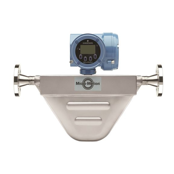
Before You Begin Specifications Full product specifications can be found in the F-Series Product Data Sheet, which is available from the Micro Motion web site at www.micromotion.com. Definitions ™ The term MVD transmitter refers to the following transmitter models: • Models 1500, 1700, 2500, and 2700 •... - Page 5 Before You Begin Figure 1 F-Series sensor with core processor Calibration tag Core processor housing Approval tag Flow direction arrow Process connection Sensor with purge fittings Purge fitting Core processor housing Purge fitting Approval tag Calibration tag Sensor Installation: F-Series...
- Page 6 Before You Begin Figure 2 F-Series sensor with integrally mounted Model 1700/2700 transmitter Model 1700/2700 transmitter Core processor housing Calibration tag Approval tag Process connection Flow direction arrow Sensor with purge fittings Model 1700 or 2700 transmitter Purge fitting Purge fitting Approval tag Calibration tag Sensor Installation: F-Series...
- Page 7 Before You Begin Figure 3 F-Series sensor with junction box Approval tag Junction box Calibration tag Process connection Flow direction arrow Sensor with purge fittings Purge fitting Junction box Purge fitting Approval tag Calibration tag Sensor Installation: F-Series...
- Page 8 Before You Begin Figure 4 F-Series sensor with integrally mounted IFT9701 transmitter Model IFT9701 transmitter Calibration tag Approval tag Process connection Flow direction arrow Sensor with purge fittings Model IFT9701 transmitter Purge fitting Purge fitting Approval tag Calibration tag Sensor Installation: F-Series...
- Page 9 Before You Begin Figure 5 High-temperature or extreme high-temperature F-Series sensor with flexible conduit Transmitter, core processor, or junction box (core processor shown) Flexible conduit Approval tag Calibration tag Process connection Flow direction arrow Sensor Installation: F-Series...
-
Page 10: Determining A Location
Determining a Location Step 1 Determining a Location Choose a location for the sensor based on the requirements described in this section. The following general guidelines can help you select an appropriate location for the sensor. Full flow tubes For optimal performance, the sensor tubes should remain full of process fluid. Hazardous area installations Make sure the hazardous area specified on the sensor approval tag is suitable for the environment in which the sensor is installed (see Figures 1–5). - Page 11 Determining a Location Figure 6 F-Series sensor ambient and process temperature limits (all models except high-temperature and extreme high-temperature models) Mount electronics remotely; use junction box 176 (80) 158 (70) 140 (60) 104 (40) 91 (33) 68 (20) 32 (0) –4 (–20) –40 (–40) –76 (–60)
- Page 12 Determining a Location Figure 7 F-Series sensor ambient and process temperature limits (high-temperature and extreme high-temperature models) 176 (80) 140 (60) 104 (40) High-temp. models 68 (20) 32 (0) Extreme high-temp. models –4 (–20) –40 (–40) –76 (–60) Mount electronics remotely; use junction box –112 (–80) –148 (–100) Maximum process temperature in °F (°C)
- Page 13 Determining a Location Maximum wiring distances If the transmitter is mounted remotely from the sensor, the maximum distance between the sensor and transmitter depends on cable type. See Table 2. For high-temperature and extreme high-temperature F-Series sensors, note the following: •...
-
Page 14: Orienting The Sensor
Orienting the Sensor Step 2 Orienting the Sensor The sensor will function properly in any orientation if the sensor tubes remain filled with process fluid. Micro Motion recommends orienting F-Series sensors as shown in Figure 8. Figure 8 Recommended sensor orientations Slurries and Gases Liquids... -
Page 15: Mounting The Sensor
Mounting the Sensor Step 3 Mounting the Sensor Use your common practices to minimize torque and bending load on process connections. Figure 9 illustrates how to mount the sensor. To reduce the risk of condensation or excessive moisture, the conduit opening should not point upward (if possible). - Page 16 Mounting the Sensor Mounting the electronics of high-temperature and extreme high-temperature sensors High-temperature and extreme high-temperature F-Series sensors come with a 32″ (812 mm) pre-installed flexible conduit. This conduit is required for agency approval. A factory-supplied Model 1700/2700 transmitter, core processor, or junction box is connected to the end of the flexible conduit.
-
Page 17: Wiring
Wiring Step 4 Wiring Improperly sealed housings can expose electronics to moisture, which can cause measurement error or flowmeter failure. Inspect and grease all gaskets and O-rings. Fully close and tighten all housing covers and conduit openings. Installation options The sensor has one of the following electronics configurations: •... - Page 18 Wiring Figure 11 Micro Motion cable gland and heat shrink 4 1/2 in (114 mm) 3/4 in (19 mm) Gland clamping Gland nut insert 7/8 in (22 mm) 7/8 in (22 mm) Gland body Shielded heat shrink 4. For connection at the core processor housing, prepare shielded cable as follows (for armored cable, omit steps d, e, f, and g): a.
- Page 19 Wiring Figure 13 Applying the heat shrink g. Position gland clamping insert so the interior end is flush with the heat shrink. h. Fold the cloth shield or braid and drain wires over the clamping insert and approximately 1/8 inch (3 mm) past the O-ring.
- Page 20 Wiring Figure 16 Connecting the wires at the core processor Terminal 1 Power supply + (Red wire) Terminal 4 RS-485B (Green wire) Terminal 3 RS-485A (White wire) Terminal 2 Power supply – (Black wire) Core processor housing internal ground screw •...
-
Page 21: Grounding
Grounding Step 5 Grounding The sensor can be grounded via the piping if the joints in the pipeline are ground-bonded. If the sensor is not grounded via the piping, connect a ground wire to the internal or external grounding screw, which is located on the core processor housing or junction box. -
Page 22: Purge Fittings
Purge Fittings Purge Fittings If the sensor has purge fittings, they should remain sealed at all times. After a purge plug has been removed, the sensor case should be purged with argon or nitrogen and resealed. Purging the case protects internal components. The sensor is purged of all oxygen and sealed at the factory. If the purge plugs are never removed, it is not necessary to purge or re-seal the sensor. - Page 23 Purge Fittings Table 4 Time required to purge F-Series sensor cases Purge rate Time Sensor model /hr (l/hr) minutes F025 20 (566) 4 1/2 F050 20 (566) 4 1/2 F100 20 (566) F200 20 (566) F300 20 (566) (1) If purge lines are being used, increase purge time to fill the additional volume. 8.
-
Page 24: Return Policy
Return Policy Return Policy Micro Motion procedures must be followed when returning equipment. These procedures ensure legal compliance with government transportation agencies and help provide a safe working environment for Micro Motion employees. Failure to follow Micro Motion procedures will result in your equipment being refused delivery. - Page 26 +31 (0) 318 495 555 +65 6777-8211 +31 (0) 318 495 556 +65 6770-8003 Micro Motion United Kingdom Micro Motion Japan Emerson Process Management Limited Emerson Process Management Horsfield Way 1-2-5, Higashi Shinagawa Bredbury Industrial Estate Shinagawa-ku Stockport SK6 2SU U.K.
Need help?
Do you have a question about the Micro Motion F-Series Sensor and is the answer not in the manual?
Questions and answers