Table of Contents
Advertisement
Quick Links
Advertisement
Table of Contents

Related Manuals for Tenma 72-2600


Summary of Contents for Tenma 72-2600
- Page 1 Digital Multimeter Model: 72-2600...
- Page 2 IMPORTANT SAFETY INFORMATION Please read these instructions carefully before use and retain for future reference. This instrument is designed and manufactured in compliance with: G84793, lEC61010-1, CAT III 600V Pollution Degree 2 and Double Insulation standards. • Check the test leads, probes and case insulation before using. If you find any breakage or abnormality, or you consider the device is broken, stop using the device immediately.
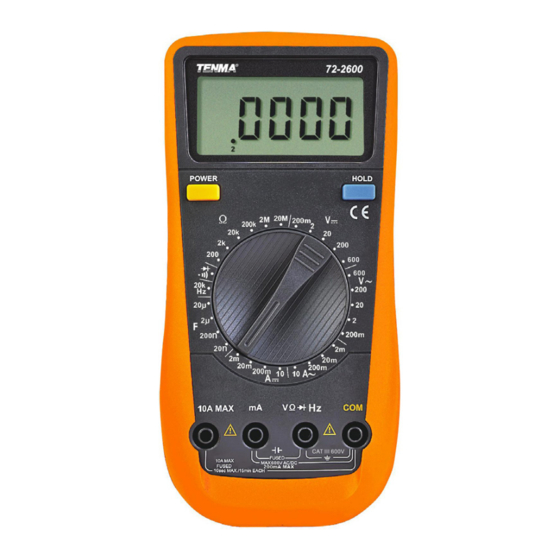
- Page 3 WHAT’S INCLUDED • Digital multimeter • User manual • Set of test leads • 9V battery (installed) FUNCTIONS LCD Display Power button HOLD button Range selector Input terminals DC VOLTAGE Input Overload Range Resolution Accuracy Impedance protection 200mV 10µV ±(0.05%+3) 100µV ±(0.1%+3) 600VAC/DC...
- Page 4 DC CURRENT Range Resolution Accuracy Overload Protection 0.1μA ±(0.5%+5) Fuse 500mA 600V 20mA 1μA 6 dia x 32mm 200mA 10μA ±(0.8%+5) Fuse 10A 600V ±(2%+10) 6 dia x 32mm • When <5A continuous measurement is allowed/ • When >5A use 10 seconds measurement at an interval of more than 15 minutes. •...
- Page 5 CAPACITANCE Range Resolution Accuracy Overload Protection 20nF 200nF 10pF ±(4.0%+20) Fuse 500mA/600V 6 dia x 32mm 2µF 100pF 20µF • Testing signal is about 400Hz 40mVrms. DIODE AND CONTINUITY Range Resolution Notes Overload Protection Display approximate Positive DC current value of forward is about 1mA and voltage drop for reverse DC voltage is...
- Page 6 Measuring DC Voltage • Insert the red test lead into the V terminal and the black test lead into COM. • Set the rotary selector to • Connect the test leads across the object to be measured in parallel and the value will be displayed.
- Page 7 Measuring Resistance • Insert the red test lead into the Ω terminal and the black test lead into the COM terminal. • Set the rotary switch to Ω resistance measurement mode. • Connect the test leads across with the object being measured. The measured value shows on the display.
- Page 8 Frequency measurement • Insert the red test lead into the Hz terminal and the black test lead into the COM terminal. • Set the rotary switch to 20kHz frequency measurement • Connect the test leads across the object being measured and the value shows on the display.
Need help?
Do you have a question about the 72-2600 and is the answer not in the manual?
Questions and answers