
Related Manuals for Tenma 72-7780


Summary of Contents for Tenma 72-7780
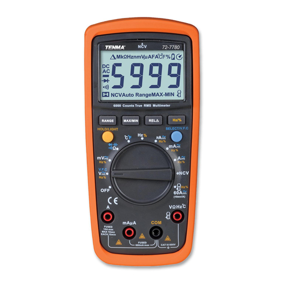
- Page 1 True RMS Digital Multimeter Model: 72-7780...
-
Page 2: Safety Information
SAFETY INFORMATION Please read these instructions carefully before use and retain for future reference. This meter is designed to meet IEC61010-1, 61010-2-032, and 61010-2-033 in Pollution Degree 2, Measurement Category (CAT II 600V, CAT III 600V) and double Insulation. • Do not operate the meter or use test leads if they appear damaged, or if the meter is not operating properly. -
Page 3: Symbol Guide
SYMBOL GUIDE AC or DC Grounding Double insulated Warning Low battery Continuity Buzzer Diode Fuse Conforms to European Union directives FUNCTIONS Casing LCD Display Function buttons x 4 Option buttons Range selector Test lead input terminals r Mk Ω Hz nm Vµ AF -8.8.8.8 MAX-MIN Auto Range NCV A Display symbol... - Page 4 Display symbol Instruction Diode measurement prompt Circuit on/off measurement prompt Relative measurement prompt Ω / kΩ / MΩ Resistance units Hz / kHz / MHz Frequency units Duty ratio measurement unit mV / V Voltage units µA/mA/A Current units nF/µF/mF Capacitance units Centigrade temperature unit Fahrenheit temperature unit...
-
Page 5: Operating Parameters
OPERATING PARAMETERS • Operating temperature: 23°C± 5°C • Relative Humidity: ≤75%. • Temperature Coefficient: 0.1× (specified accuracy)/1°C DC VOLTAGE Range Resolution Accuracy Overload Protection 60.00mV 10µV ±(0.5%+2) 600.00mV 0.1mV 6.000V 600V DC/AC 60.00V 10mV ±(0.7%+3) 600.0V 0.1V 600V Note: The input impedance is 10MΩ. AC VOLTAGE Range Resolution... - Page 6 DIODE AND CONTINUITY Range Resolution Accuracy Overload Protection When ≤10Ω, the 0.1Ω 600Vp buzzer beeps. Notes: • The open circuit voltage is about *1V. • The buzzer may beep when the resistance of a circuit under test is <10Ω. • The buzzer does not beep when the resistance of a circuit under test is higher than 150Ω.
-
Page 7: Temperature Measurement
DC CURRENT Range Resolution Accuracy Overload Protection 600.0µA 0.1µA 6000µA 1µA ±(0.7%+2) 600V DC/AC 60.00mA 10µA Fuse 0.6A 600.0mA 0.1mA Fuse 10A 6.000A ±(1.0%+3) 10.00A 10mA AC CURRENT Range Resolution Accuracy Overload Protection 600.0µA 0.1µA 6000µA 1µA ±(1.0%+3) 600V DC/AC 60.00mA 10µA (<1A range) Fuse 0.6A... -
Page 8: Operation
OPERATION Measuring DC/AC Voltage • To measure DC/AC voltage, perform the following steps: Insert the red test lead into the VΩHz C terminal and the black test lead into the COM terminal. Turn the range selector to mV ~ measurement mode and connect the test probes in parallel with the object being measured. -
Page 9: Measuring Continuity
Measuring Continuity • To measure continuity, perform the following steps: Insert the red test lead into the VΩHz C terminal and the black test lead into the COM terminal. Turn the range selector to measurement mode and connect the test probes to the object being measured. - Page 10 Capacitance measurement • To measure the resistance, perform the following steps: Insert the red test lead into the VΩHz C terminal and the black test lead into the COM terminal. Turn the range selector to , the meter and leads will display a fixed internal capacitance.
- Page 11 Connect the test leads to the circuit to be measured in series. Alternatively connect the current clamp to the VΩHz C terminal and the COM terminal. Turn the rotary switch to to measure up to 60A AC or DC. Open the clamp jaws and pass the cable into the clamp and close the jaws.
-
Page 12: Specifications
SPECIFICATIONS Function Range/description Operating Temperature: C (32 F~104 Relative Humidity: ≤75%@ 0 C~30 ≤50%@ 30 C~40 Operating ASL: 0~2000m Battery Type: 2 off 1.5V AA Dimensions (H x W x L): 175 x 80 x 48mm Weight: 350g incl battery Range: Auto Polarity:...
Need help?
Do you have a question about the 72-7780 and is the answer not in the manual?
Questions and answers