Table of Contents
Advertisement
Advertisement
Table of Contents

Related Manuals for Tenma 72-3540


Summary of Contents for Tenma 72-3540
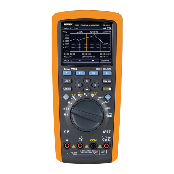
- Page 1 True RMS Datalogging Multimeter Model: 72-3540...
-
Page 2: Table Of Contents
CONTENTS Page Number Details Important Safety Information What’s Included Product Overview Buttons Input Terminals Rotary Switch General Specification Electrical Specification AC Voltage DC Voltage AC Voltage + DC Voltage AC Current DC Current AC Current + DC Current Resistance Capacitance Conductance Temperature Frequency... - Page 3 Page Number Details Diode Frequency / Duty Cycle Measurement / Pulse Width Temperature LPF Measurement Maximum & Minimum Value Relative Value Peak Detection Compare Mode Comp Recording Measurement Data Communication Cleaning & Maintenance Charging the Battery...
-
Page 4: Important Safety Information
Please read these instructions carefully before use and retain for future reference. IMPORTANT SAFETY INFORMATION • When using electrical appliances basic safety precautions should always be followed. • Never use a damaged meter. Before use, always check the meter case for cracks or any missing parts. -
Page 5: What's Included
WHAT’S INCLUDED • One Datalogging Multimeter • One charging adaptor • A pair of test leads • One charging connector • Two K type temperature probes • One USB cable • One user manual • One CD • One temperature connector •... -
Page 6: Buttons
BUTTONS Button Function Turn on or off the meter power. Select the sub-functions and modes related to the functions of the F1 F2 F3 F4 rotary switch. Cursor buttons are used to select menu items, scroll reading information and input data. HOLD Keep the current reading on the display. -
Page 7: Rotary Switch
ROTARY SWITCH Switch Symbol Function Ṽ Measurement of AC voltage. mṼ Measuremnt of mV in AC and mV in AC+DC. Measurement of voltage in DC and AC+DC. mV °C °F Measurement of mV in AC and temperature. ΩnS Measurement of resistance, continuity and specific conductance. Diode test and capacitance measurement. -
Page 8: Electrical Specification
No specified index for RF-field over 1V/m Operating altitude 0~2000m 0.1 x (specified accuracy)/°C (<18°C or Temperature coefficient >28°C) Internal battery Lithium battery of 7.4V~2200mAh Power adaptor Input of 100V~240V, 50/60Hz External diameter and internal 5.5mm (external) 2.5mm (internal) diameter Low battery symbol shows on the LCD Dimensions... -
Page 9: Dc Voltage
45~1kHz 1k~10kHz 10k~20kHz 20k~100kHz 600V 0.01V Only for ±(0.3% + 30) ±(1.2% + 40) ±(3% + 40) reference 45~1kHz 1k~5kHz 5k~10kHz 10k~100kHz 1000V 0.1V Only for ±(0.6% + 30) ±(3% + 40) ±(6%+40) reference • Input impedance: about 10MΩ. • Overload protection: 1000V. -
Page 10: Ac Current
AC CURRENT Range Resolution Accuracy Tolerance: ± (% reading + digits) 45~1kHz 1k~10kHz 600µA 0.01µA ±(0.6% + 40) ±(1.2%+40) 45~1kHz 1k~10kHz 6000µA 0.1µA ±(0.6%+20) ±(1.2%+40) 45~1kHz 1k~10kHz 60mA 0.001mA ±(0.6%+40) ±(1.2%+40) 45~1kHz 1k~10kHz 600mA 0.01mA ±(0.6%+20) ±(1.2%+40) 45~1kHz 1k~10kHz 0.001A ±(1%+20) ±(3%+40) •... -
Page 11: Resistance
50~1kHz 1k~10kHz 60mA 0.001mA ±(0.8% + 40) ±(2.0%+40) 50~1kHz 1k~10kHz 600mA 0.01mA ±(0.8% + 20) ±(2.0% + 40) 50~1kHz 1k~10kHz 600V 0.001A ±(1.2% + 20) ±(3% + 40) • Display: true virtual value for 10% to 100% of the range. •... -
Page 12: Conductance
CONDUCTANCE Range Resolution Accuracy tolerance: ± (% reading + digits) 60NS 0.01NS ± (2% + 10) • Overload protection: 1,000V. • Humidity for 60MΩ: <50%. TEMPERATURE Range Resolution Accuracy tolerance: ± (% reading + digits) -40°C~40°C ± (2.0% + 30) 40°C~400°C ±... -
Page 13: Pulse Width
PULSE WIDTH Range Resolution Accuracy tolerance: ± (% reading + digits) 250mS 0.001mS~0.01mS ± (1.2% + 30) • Overload protection: 1000V. • When the rise time is less than 1µs, the signals centre on the trigger level. • The pulse width is greater than 2µs for 10Hz to 200kHz. The pulse width depends on signal frequency. -
Page 14: Meter Settings
Symbol Battery capacity • When the battery capacity is lower Full capacity than 3% of full capacity the meter will Half capacity automatically shutdown. Empty Backlight Control • If the display is not visible in low-light situations, press to switch the backlight brightness. - Page 15 • Use the left and right directional buttons to select the required edit position, then press the up and down directional buttons to enter different numbers. • Press the function button OK to confirm. • To cancel the settings, press the function button CANCEL. Auto Power Save •...
-
Page 16: Ac Voltage
AC VOLTAGE • Insert the red test lead into the V terminal and the black test lead into the COM terminal. • Set the rotary switch to Ṽ or mṼ as shown in the image below. • Read the measured voltage values on the display. True virtual values are displayed for AC measurement. -
Page 17: Ac & Dc Current
Warnings • Do not input a voltage higher than 1000V. Higher voltage may be measured but it risks damaging the meter. • When measuring high voltage, extra care should be taken to avoid an electric shock. • After completing all the measuring operations, disconnect the connection between the test leads and the circuit under test. -
Page 18: Conductance
maximum range of the meter, “OL” will show on the display. • When measuring in-circuit resistance, all of the power within the measured circuit must be shut off before measurement and all of the capacitors must be discharged to ensure a correct measurement. -
Page 19: Capacitance
CAPACITANCE • Insert the red test lead into the terminal and the black test lead into the COM terminal. • Set the rotary switch to the measurement press the SELECT button to select capacitance measurement. • Connect the test leads to both ends of the measured capacitance (see right). -
Page 20: Diode
DIODE • Insert the red test lead into the terminal and the black test lead into the COM terminal. The polarity of the red test lead is positive, and negative for the black test lead. • Set the rotary switch to the measurement where the diode measuring mode is default. -
Page 21: Temperature
TEMPERATURE • Set the rotary switch to the measurement function “mV °C °F” then press the SELECT button to choose between celsius (°C) or fahrenheit (°F). • Insert the temperature connector into four terminals and connect two temperature probes to the temperature connector. •... -
Page 22: Dbv
• Do not input a voltage above 1000V. Higher voltage may be measured but it poses the risk of damaging the meter. • After completing all of the measurement operations, disconnect the connection between the test leads and the circuit under test. •... -
Page 23: Relative Value
RELATIVE VALUE • Press the function button MENU to enter the next interface, then press the function button REL to enter the measuring mode of relative values, then press the function button REL to activate the measurement of relative values. •... -
Page 24: Recording Measurement Data
measurement of compare mode. Press the function button EXIT to exit the measurement of compare mode. RECORDING MEASUREMENT DATA • Press the function button SAVE to enter the modes of single recording, continuous recording and inquire recording. Press the cursor buttons to select the following modes: Save •... - Page 25 - Set Duration • Press the function button EDIT to set the duration time of continuous recording. • Press or hold the ◄ or ► buttons to move the cursors to select edit locations. • Press or hold the ▲ or ▼ buttons to enter different numbers. The duration time can be set as days, hours and minutes.
-
Page 26: Communication
• Press the function button PREV to display basic information on the previous record. • Press the function button NEXT to display the basic information on the next record. • Press the function button RETURN to go back to the previous menu. •... -
Page 27: Cleaning & Maintenance
CLEANING & MAINTENANCE General Maintenance • Clean the meter casing with a damp cloth and a mild detergent. • Do not use any chemicals, abrasives or solvents that could damage the meter. • Dirt or moisture on the terminals can affect readings. Clean the terminals according to the following steps: - Turn off the meter and remove all test leads. -
Page 28: Charging The Battery
CHARGING THE BATTERY • When the battery indicator, in the top right hand corner of the display is less than 5% of full capacity, the meter should be immediately charged, otherwise it will affect the measurement accuracy. • Set the rotary switch to “CHG” and the display will read “please plug in AC adapter!”...
Need help?
Do you have a question about the 72-3540 and is the answer not in the manual?
Questions and answers