Table of Contents
Advertisement
Quick Links
Advertisement
Table of Contents

Related Manuals for Tenma 72-3097


Summary of Contents for Tenma 72-3097
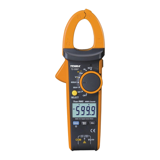
- Page 1 600A True RMS Digital Clamp Meter Model: 72-3097 & 72-3099...
-
Page 2: Table Of Contents
CONTENTS Page Number Details Important Safety Information Product overview Key Functions General Specification Electrical Specification AC (Ã) AC (A) (72-3099 only) AC Voltage (Ṽ) DC Voltage (V) Resistance (Ω) Continuity Test Diode Test Capacitance Temperature (°C) (72-3099 only) Frequency (Hz) (72-3099 only) Operation - AC Measurement DC Current Measurement (72-3099 only) AC Voltage Measurement... -
Page 3: Important Safety Information
IMPORTANT SAFETY INFORMATION • When using electrical appliances basic safety precautions should always be followed. • Check the clamp ammeter and test pen before use. If there is any damage or any abnormalities, do not use it. • Do not use the clamp ammeter if the battery cover and rear cap is not in place, as there is a risk of electric shocking. -
Page 4: Product Overview
PRODUCT OVERVIEW Clamp head: a device used to measure AC/DC current and convert current into voltage. Clamp body: designed for safe use and to protect the operator from touching dangerous areas. Clamp head pulling handle: press the trigger to open the clamp head. -
Page 5: General Specification
Sampling rate About 3/s. Sensor type Coil induction (72-3097)/Hall effect sensor (72-3099). An additional reading error of ±1.0% may result when Text position error the power to be measured is not clamped at the centre of the clamp head. -
Page 6: Ac (A) (72-3099 Only)
• The measurement accuracy of non-sinusoidal wave various frequency current should be 5% higher than the former. AC (A) (72-3099 only) Range Resolution Accuracy Overload protection • DCI base number 60.00A 0.01A should be deleted by ± (2.5% + 5) 600A the ZERO key. -
Page 7: Diode Test
Open circuit voltage is about 3.3V, measurable PN knot ≤3V positive 100V DC 6.000V 0.001V pressure drop value. Silicon PN 750V AC normal voltage value is about 0.5~0.8V. CAPACITANCE 72-3097 Range Resolution Accuracy Overload protection 99.99nF 0.01nF ± (4.0% + 25) 999.9nF 0.1nF 9.999µF... -
Page 8: Frequency Hz (72-3099 Only)
FREQUENCY Hz (72-3099 ONLY) Range Resolution Accuracy Overload protection 10Hz 0.01Hz 1000V DC ± (0.1% + 4) 1 MHz 1kHz 750V AC Requirement on input range: • ≤ 100kHz: 100mVrms ≤ input range ≤ 20Vrms > 100kHz ~ 1MHz: 200mVrms ≤ input range ≤... -
Page 9: Dc Current Measurement (72-3099 Only)
DC CURRENT MEASUREMENT (72-3099 ONLY) • Push the switch to DC current gear. If the LCD display is not set to zero, press REL to clear. • After measuring the big current gear, the clamp head will be left with remanence and the LCD will have base values. -
Page 10: Dc Voltage Measurement
• Pay attention to electric shocks when measuring high voltage. • After completing all measurement operations, disconnect the test pen from the measured circuit. • When the measured voltage is higher than the safety voltage of 30V AC, the meter LCD displays the high voltage warning prompt. -
Page 11: Continuity Test
select resistance measurement Ω and connect the test pen in parallel with the two terminals of measured resistance. • Directly read the measured resistance value from the display. Note: • If the open circuit of resistance being measured exceeds the maximum range of the meter, the display will show “OL”. -
Page 12: Capacitance Measurement
• For silicon PN junction generally 500~800mV is confirmed to be the normal value. Note: • “OL” will be displayed when the measured diode is open-circuit or the polarity is inversely connected. • Before measuring diode, the power circuits being measured shall be powered off and all capacitors shall release residues of electric charged to assure the measurement accuracy,... -
Page 13: Frequency
FREQUENCY • Insert the red test pen into the “Hz” jack and the black test pen into the “COM” jack. • Push the range switch to the measurement gear “Hz” and connect the test pen in parallel with the signal source to be measured. -
Page 14: Power Gear (Off) & Automatic Shutdown
POWER GEAR (OFF) & AUTOMATIC SHUTDOWN • The instrument should be powered off. • If you’re not turning the knob switch or pressing the key to the clamp ammeter within the user-defined shutdown time (default 15 mins), the display will be blank and enter the low power consumption dormant state.
Need help?
Do you have a question about the 72-3097 and is the answer not in the manual?
Questions and answers