Sign In
Upload
Manuals
Brands
Advantech Manuals
Motherboard
ASMB-786G2-00A1
Advantech ASMB-786G2-00A1 Manuals
Manuals and User Guides for Advantech ASMB-786G2-00A1. We have
1
Advantech ASMB-786G2-00A1 manual available for free PDF download: User Manual
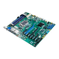
Advantech ASMB-786G2-00A1 User Manual (136 pages)
LGA 1151 Intel Xeon E/8th Gen Intel Core Series ATX Server Board with DDR4, 7 x PCIe, 6 x USB 3.1, 8 x SATAIII, Quad/Dual LANs, and IPMI
Brand:
Advantech
| Category:
Motherboard
| Size: 10 MB
Table of Contents
Table of Contents
7
Chapter 1 Hardware Configuration
11
Introduction
12
Features
12
Specifications
13
Cpu
13
Pch
13
Memory
13
Input/Output
13
Graphics
14
Ethernet LAN
14
Industrial Features
14
Mechanical and Environmental Specifications
14
Jumpers and Connectors
15
Jumper and Connector Locations
17
Onboard LAN LED Definition
18
Onboard Leds (LED2, LED3, and LED4)
18
ASMB-786 Block Diagram
19
Safety Precautions
20
Jumper Settings
20
How to Set Jumpers
20
Table 1.5: CMOS Clear (JCMOS1)
21
Sysfan_Sel1)
22
Table 1.8: USB Power Switch (JUSB1/JUSB2)
22
Table 1.10: ATX/AT Mode Selector (PSON1)
23
System Memory
24
Chapter 2 Connecting Peripherals
25
Introduction
26
USB Ports (LAN1_USB1_2, LAN2_USB3_4, USB5~13)
26
USB Power Switch (JUSB1, JUSB2)
27
Display Connector (HDMI1_VGA1, DVI1)
28
Serial Ports (COM1 ~ COM2)
29
External Keyboard and Mouse (KBMS1)
30
CPU Fan Connector (CPUFAN0)
31
System FAN Connector (SYSFAN0 ~ SYSFAN3)
32
Front Panel Connectors (JFP1, 2, 3)
33
Power LED (JFP3 Pins 1, 3)
34
External Speaker (JFP2 Pins 1, 4, 7, 10)
34
HDD LED Connector (JFP1 Pins 2, 5)
34
SNMP Smbus Connector (JFP2 Pins 8, 11)
34
ATX Soft Power Switch (JFP1 Pins 3, 6)
34
Reset Connector (JFP1 Pins 9, 12)
34
Alarm Board Connector (VOLT1)
35
Case Open Connector (JCASE1)
36
Front Panel LAN Indicator Connector (LANLED1)
37
Serial ATA Interface (SATA0 ~ 7)
38
Pcie X16 Expansion Slots
39
Pcie X4 Expansion Slots (Pciex4_Slot2, 7)
41
Pcie X1 Expansion Slots (Pciex1_Slot1, 3, 5)
42
Auxiliary Power Connector (ATX12V1)
43
SPI Flash Connector (SPI_CN1)
44
Low-Pin-Count Connector (LPC1)
45
Parallel Port (LPT1)
46
PMBUS Connector (PMBUS1)
47
BIOS Operation
49
Chapter 3 BIOS Operation
49
Introduction
50
Entering BIOS Setup
51
Main Menu
51
System Time/System Date
51
Advanced BIOS Features
52
Platform Misc Configuration
53
CPU Configuration
54
Power and Performance
55
PCH-FW Configuration
56
Trusted Computing
64
ACPI Settings
65
SMART Settings
66
COM1/2 Configuration
67
NCT6776 HW Monitor
70
PCA-COM232/COM485 Super I/O Configuration
73
Serial Port Console Redirection
75
Intel® Trusted Execution Technology (TXT) Information
78
PCI Subsystem Settings
79
USB Configuration
80
UEFI Network Stack Configuration
83
CSM Configuration
84
Chipset
89
System Agent (SA) Configuration
89
PCH-IO Configuration
94
Figure 3.23PCI Express Configuration Screen
96
Figure 3.24SATA and RST Configuration Screen
97
Figure 3.25USB Configuration Screen
98
Figure 3.26Security Configuration Screen
99
Figure 3.27HD Audio Configuration Screen
100
Security
101
Boot
102
Save and Exit
103
Server Management
104
System Event Log
106
BMC Self-Test Log
108
BMC Network Configuration
109
Chapter 4 Driver Installation
111
Before Installation
112
Introduction
112
Chipset
112
Graphics
113
Lan
113
HD Audio
113
Intel® ME
113
Sata Raid
114
Appendix A Watchdog Timer
115
Watchdog Timer Overview
116
Programming the Watchdog Timer
116
Example Programs
118
Table A.1: Watchdog Timer Registers
118
Appendix B I/O Pin Assignments
123
USB 2.0 Header (USB7 ~ 12)
124
USB 3.1 Header (USB5_6)
124
VGA Connector (VGA1)
125
Interface (COM1 ~ 2)
125
External Keyboard/Mouse Connector (KBMS1)
126
System Fan Power Connector (SYSFAN0 ~ 3)
126
Power LED and Keyboard Lock (JFP3)
126
External Speaker Connector (JFP2)
127
HDD LED Connector (JFP2)
127
SNMP Smbus Connector (JFP2)
127
ATX Soft Power Switch (JFP1)
128
Reset Connector (JFP1)
128
Front Panel Audio Connector (FPAUD1)
128
8-Pin Alarm Board Connector (VOLT1)
129
Case Open Connector (JCASE1)
129
Front Panel LAN LED Connector (LAN_LED1)
129
SPI Flash Card Pin Connector (SPI_CN1)
130
GPIO Connector (GPIO1)
130
SMBUS Connector (SMBUS1)
130
B.17 SPI Flash Card Pin Connector (SPI_CN1)
130
PMBUS Connector (PMBUS1)
131
Parallel Port (LPT1)
131
System I/O Ports
132
Interrupt Assignments
132
B.22 System I/O Ports
132
First Motherboard Memory Map
133
Advertisement
Advertisement
Related Products
Advantech ASMB-785
Advantech ASMB-786
Advantech ASMB-788
Advantech ASMB-786G4-00A1
Advantech ASMB-920IR
Advantech ASMB-820I
Advantech ASMB-584
Advantech ASMB-585
Advantech ASMB-925I-00A1
Advantech ASMB-586
Advantech Categories
Motherboard
Computer Hardware
Desktop
Touch Panel
Network Router
More Advantech Manuals
Login
Sign In
OR
Sign in with Facebook
Sign in with Google
Upload manual
Upload from disk
Upload from URL