Viconics VTR7300 Series Manual
Pir ready terminal equipment controllers for commercial and lodging hvac fan coil applications
Hide thumbs
Also See for VTR7300 Series:
- Installation manual (10 pages) ,
- Installation manual (25 pages)
Advertisement
Quick Links
Download this manual
See also:
Installation Manual
Product overview
The VTR73XX Series Fan Coil Terminal Equipment Controller used in conjunction with
the VC3000 Series Line Voltage Switching Relay Packs is specifically designed for fan
coil control applications. They can be used both for new or retrofit applications. In
retrofit applications, they can re-use the existing wires between the old line voltage
switching thermostat and the fan coil thus saving on the installation of any new wires.
Stand-alone and network operation are available.
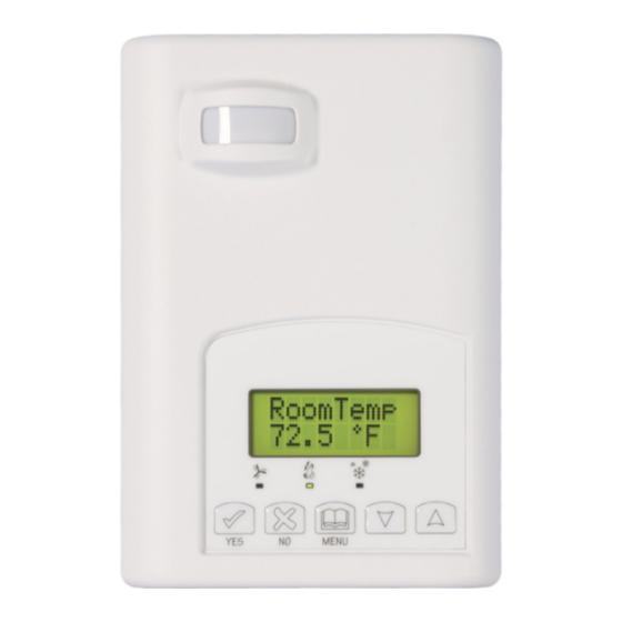
The VTR73XX Series Fan Coil Terminal Equipment Controller features a backlit LCD
display with dedicated function menu buttons for simple operation. Accurate
temperature control is achieved due to the product's PI proportional control algorithm,
which virtually eliminates temperature offset associated with traditional, differential-
based Terminal Equipment Controllers. All models feature configurable System and
Fan button functions to meet all possible applications The VTR73XX Terminal
Equipment Controllers are powered and communicate with the associated VC3000 Series Transformer Relay Pack(s) using
only 3 wires.
2 types of interfaces for the user can be ordered. The VC73x5 models are typically used for hotel and lodging applications
where the middle button of the interface is for the user to select the local displayed scale in ºF or ºC. The VC73x0 models are
typically used for commercial and institution applications where the middle button of the interface is defined for the local
unoccupied override function.
The VTR73XX Terminal Equipment Controllers are also compatible with the new Viconics PIR cover accessories. Terminal
Equipment Controllers equipped with a PIR cover provide advanced active occupancy logic, which will automatically switch
occupancy levels from Occupied to Stand-By and Unoccupied as required by local activity being present or not. This advanced
occupancy functionality provides advantageous energy savings during occupied hours without sacrificing occupant comfort. All
Terminal Equipment Controllers can be ordered with or without a factory installed PIR cover ( see ordering notes below ).
The compatible VC3000 Series Line Voltage Switching Transformer Relay Pack(s) operate as slave unit(s) under the control of
a single master VTR73XX Terminal Equipment Controller. A single VTR73XX Terminal Equipment Controller can control up to
10 VC3000 Series Relay Pack. The VC3000 Series Relay Packs are line-powered units. They locally contain all the relay
outputs for fan switching and valve control. Models are also available for extra monitoring / control inputs of the Fan Coil Units.
The additional following documents are available at:
•
PIR Hospitality application information and examples, are available on document: APP-HOSPITALITY-PIR-VTR73-Guide-Exx
•
HVAC Fan Coil application information and examples, are available on document: APP-VTR7300-PIR-Exx
•
Information on installation of the Transformer Relay Pack (VC3000E), is available on document LIT-VC3000-Exx
•
PIR cover installation information is available on document: PIR Cover Installation-Exx
•
Information on the BACnet models (VTR73xxX5x00B), is available on document ITG-VTR73-PIR-BAC-Exx
•
Information on the Wireless models (VTR3xxX5x00W), is available on documents: ITG-VWG-40-BAC-Exx and MAN Wireless Stat Driver
Guide-Exx
VTR73XXA models available
Viconics part number
Primary market
User interface definition
On board %RH sensor
For dehumidification strategy
Ordering Information Notes:
The (X) at the end of the model number represents available communication options:
•
X = none for Stand-alone
The Terminal Equipment Controllers can be ordered with a factory installed PIR cover. Please use (5500) extension instead of
the (5000) only extension. The Terminal Equipment Controllers ordered without a PIR cover can be retrofitted with a separate
PIR accessory cover afterwards if required.
Ordering examples:
• A VTR7305AW5500B is for a wall mounted Terminal Equipment Controller with a hotel / lodging interface with a factory
mounted PIR cover and an MS-TP BACnet communication interface.
• A VTR7350A5000W is for a wall mounted Terminal Equipment Controller with a commercial / institution interface and a
wireless communication interface. The Terminal Equipment Controller can be retrofitted with a separate PIR accessory
cover afterwards if required.
028-0298_R0_LIT-VTR7300-PIR-E00.doc
For Commercial and Lodging HVAC Fan Coil Applications
www.viconics.com
VTR7300A5x00(x)
VTR7350A5x00(x)
Commercial and institution applications
None
• X = B for BACnet MS-TP
PIR Ready VTR7300 Series
Terminal Equipment Controllers
(Issue Date: March 29, 2010 – 028-0298_R0)
VTR7305A5x00(x)
Hotels and lodging applications
Yes
None
• X = W for Wireless
VTR73x5X Lodging
VTR73x0X Commercial
VTR7355A5x00(x)
Yes
www.viconics.com / sales@viconics.com
Advertisement

Related Manuals for Viconics VTR7300 Series


Summary of Contents for Viconics VTR7300 Series
- Page 1 The VTR73XX Terminal Equipment Controllers are also compatible with the new Viconics PIR cover accessories. Terminal Equipment Controllers equipped with a PIR cover provide advanced active occupancy logic, which will automatically switch occupancy levels from Occupied to Stand-By and Unoccupied as required by local activity being present or not.
- Page 2 Operation overview The VC3xxxX Series Line Voltage Switching Transformer Relay Pack(s) operate as slave unit(s) under the control of a single master VTR73xxA Terminal Equipment Controller. Fan operation can be configured and wired for the following: 3 Speed configuration using 3 fan relays ( Low – Med - High ) 2 Speed configuration using 2 fan relays ( Low - High ) 3 Speed configuration with Auto fan speed mode using 3 fan relays ( Low –...
- Page 3 Configurable BI, RBI, UI, RUI inputs overview RUI1, Remote universal input #1 on VC3xxxX can be configured for the following functions: BI1, Binary input #1 can be configured for the following functions: (Filter): a backlit flashing Filter alarm will be displayed (None): No function will be associated with the input on the Terminal Equipment Controller LCD screen when the input is energized.
- Page 4 VTR73xxA Terminal Equipment Controller Installation Remove security screw on the bottom of Terminal Equipment Controller cover. • Open up by pulling on the bottom side of Terminal Equipment Controller. • Remove Assembly and remove wiring terminals from sticker. (Fig. 3) •...
- Page 5 VTR73xxA Terminal Equipment Controller Terminal Identification and Function Terminal Identification All VTR73xxA5x00(X) Terminal Equipment Controller Terminal 3 Tx – Rx Communication Terminal 4 Power Hot 7.0 Vdc Terminal 5 Power Common Terminal 13 BI 1 ( Configurable ) Terminal 14 Scom Terminal 15 BI 2 ( Configurable )
- Page 6 Programming and status display instructions Status display The VTR73xxA Terminal Equipment Controller features a two-line, eight-character display. There is a low-level backlight level that is always active and can only be seen at night. When left unattended, the Terminal Equipment Controller has an auto scrolling display that shows the actual status of the system.
- Page 7 User interface • Unoccupied mode Override An Override can be made on commercial models during an Unoccupied period. If the Override option is enabled in the lockout configuration pressing the middle override button will resume occupied setpoints for a time specified by parameter ToccTime •...
- Page 8 • Mode button menu sequence. Modes presented to the user are dependent on sequence of operation selected Default mode is in bold when sequence of operation parameter is changed AutoMode set to On = Auto system mode active. Sequence selected Mode Menu 0 = Cooling Only Off - Cool...
- Page 9 ), be sure you set the SAME channel value both at the gateway and the Terminal Equipment Controller(s). Viconics recommends using only the 2 last channels ( 25-2575MHz and 26- 2580MHz ) The default value of 10 is NOT a valid channel. The valid range of available...
- Page 10 Conditional parameter to Wireless models VTR73xxX5x00W Get From Terminal Equipment Controller Get From another device Entering a MAC address enables an automatic routine that automatically fetches configuration utility all the required configuration property of the current device from another one Default value = 0 already configured to the same required property values.
- Page 11 (None): No function will be associated with the input. Input can be used for remote RUI 1 Remote Universal input no.1 network monitoring. configuration Default value = None (COC/NH) Change over dry contact. Normally Heat: Used for hot / cold water or air change over switching in 2 pipe systems.
- Page 12 • °F for Fahrenheit scale C or F • °C for Celsius scale Sets scale of the Terminal Equipment Controller On hotel models, this sets the default value when the Terminal Equipment Default value = °F Controller powers up Conditional parameter to Humidity models VTR735xX5x00(X) %RH disp Local %RH Display Enables the display of humidity below the room temperature on the display...
- Page 13 Conditional parameter to Humidity models VTR735xX5x00(X) DHumiLCK Typically toggled through the network. Dehumidification lockout This variable enables or disables dehumidification based on central network requirements from the BAS front end Default value: On = Authorized • On = Dehumidification Authorized •...
- Page 14 Adjust the proportional band used by the Terminal Equipment Controller PI control Pband Proportional band setting loop. Default is : 3 Warning. Note that the default value of 3.0 °F ( 1.2 °C ) gives satisfactory operation in most normal installation cases. The use of a superior proportional band different than the factory one is normally warranted in applications where the Terminal Equipment Controller location is problematic and leads to unwanted cycling of the unit.
- Page 15 Will set the maximum number cycles per hour under normal control operation. It Cool cph Cooling output cycles per hour represents the maximum number of cycles that the equipment will turn ON and OFF in one hour. Default value = 4 C.P.H. Note that a higher C.P.H will represent a higher accuracy of control at the expense of wearing mechanical components faster.
- Page 16 VTR73xxA Terminal Equipment Controller Specifications Terminal Equipment Controller power requirements: 7.0 Vdc +/- 10% 2.4 watts minimum Operating conditions: 0 °C to 50 °C ( 32 °F to 122 °F ) 0% to 95% R.H. non-condensing Storage conditions: -30 °C to 50 °C ( -22 °F to 122 °F ) 0% to 95% R.H.
Need help?
Do you have a question about the VTR7300 Series and is the answer not in the manual?
Questions and answers