Viconics VT8600 Series Installation Manual
Rooftop unit, heat pump and indoor air quality controller
Hide thumbs
Also See for VT8600 Series:
- Installation manual (10 pages) ,
- User interface manual (96 pages)

Subscribe to Our Youtube Channel
Related Manuals for Viconics VT8600 Series


Summary of Contents for Viconics VT8600 Series
- Page 1 VT8600 Series Installation Guide Rooftop Unit, Heat Pump and Indoor Air Quality Controller...
- Page 2 Installation Guide VT8600 Series • If replacing an existing Room Controller, label wires before removal of Controller. • Electronic controls are static sensitive devices. Discharge yourself correctly before manipulating and installing Room Controller. • A short circuit or wrong wiring may permanently damage Room Controller or equipment.
-
Page 3: Installation
Installation Guide VT8600 Series INSTALLATION Remove security screw (if any) on bottom of Room Controller cover. Open unit by pulling on bottom side of Room Controller (Figure 1). Read FCC ID and IC label installed in cover before installing any wireless product. -
Page 4: Terminal Identification & Function
Installation Guide VT8600 Series TERMINAL IDENTIFICATION & FUNCTION VT86xxU Used in applications Description / Application IAQ, HP & RTU Internal Temperature 1- BO1 2- BO2 3- BO3 4- BO4 5- RC RC (24 Vac) 6- C Common 7- RH 8- BO8... -
Page 5: Typical Applications
Installation Guide VT8600 Series TYPICAL APPLICATIONS VT8600 RTU: 2 Heating Stages / 2 Cooling Stages AIR FLOW MEASURING STATION (0-10 VDC) 1 2 3 4 5 6 7 8 9 10 11 12 TRANSMITTER (0-10 VDC) ECONO FILTER SENSOR SENSOR... - Page 6 Installation Guide VT8600 Series VT8600 RTU: 2 Cooling Stages / Modulating Heat AIR FLOW MEASURING STATION (0-10 VDC) 1 2 3 4 5 6 7 8 9 10 11 12 Mod. Heat TRANSMITTER (0-10 VDC) (0-10 VDC) ECONO FILTER SENSOR...
- Page 7 Installation Guide VT8600 Series VT8600 HPU: 2 Compressors, Auxiliary Heat and Economizer AIR FLOW MEASURING STATION (0-10 VDC) 1 2 3 4 5 6 7 8 9 10 11 12 TRANSMITTER (0-10 VDC) ECONO FILTER SENSOR SENSOR 13 14 15 16 17 18 19 20 21 22 23 24 Viconics Technologies Inc.
-
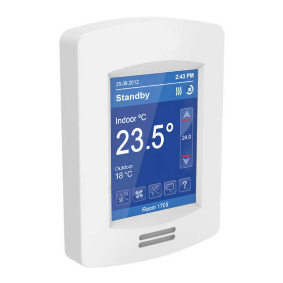
Page 8: Home Screen Display
Installation Guide VT8600 Series HOME SCREEN DISPLAY Typical Hospitality User Interface Shown Time Date System Status Occupancy Status Fan Status Up Arrow Increase Temperature Setpoint Indoor Temperature Actual Setpoint Down Arrow Outdoor Temperature Decrease Temperature Setpoint Help System Mode Short Network... -
Page 9: How To Enter Set-Up Screen
Touch and hold this point For more information on using and configuring the functions of the HMI, for 3 seconds to enter set-up mode refer to the VT8600 Series User Interface Guide NOTE: If a configuration/installer password is activated to prevent... -
Page 10: Appendix A Terminal Correspondence
VT7000 series Room Controllers. There is a direct correspondence of functions between the terminals of the VT7000 series and the VT8600 series. Consult the table below to verify the appropriate terminal when replacing a VT7000 Room Controller with a VT8600 Room Controller.
Need help?
Do you have a question about the VT8600 Series and is the answer not in the manual?
Questions and answers