Table of Contents
Advertisement
Quick Links
Download this manual
See also:
Manual
C
ONTENTS
Installation
Installation
1 | PIR Ready VTR7300 Series-Installation Guide
PIR Ready VTR7300 Series
Terminal Equipment Controller
Installation Guide
F o r C o m m e r c i a l a n d L o d g i n g H V A C
F a n C o i l Ap p l i c a t i o n s
M a y 3
2
2
2
3
5
6
6
6
7
7
8
8
8
10
10
11
11
11
11
12
13
Advertisement
Table of Contents

Subscribe to Our Youtube Channel
Related Manuals for Viconics VTR7300 Series


Summary of Contents for Viconics VTR7300 Series
-
Page 1: Table Of Contents
Configuring and Status Display Instructions Status display User Interface Local keypad interface Dual occupied setpoints adjustment Single occupied setpoints adjustment Unoccupied and stand-by setpoints adjustments Mode button menu sequence. Installer Configuration Parameter Menu Configuration interface 1 | PIR Ready VTR7300 Series-Installation Guide... -
Page 2: Location
Strip each wire 1/4 inch from end. 10. Insert each wire according to wiring diagram. 11. Gently push excess wiring back into hole (fig. 3). 2 | PIR Ready VTR7300 Series-Installation Guide... -
Page 3: M A Y 3 R D , 2 0 1 2 / 0 2 8 - 0 2 9 8 - R
A short circuit or wrong wiring may permanently damage the Terminal Equipment Controller or the equipment. All VTR7300 series controls are designed for use as operating controls only and are not safety devices. These instruments have undergone rigorous tests and verification prior to shipping to ensure proper and reliable operation in the field. - Page 4 2 Power Hot 7.0 VDC 4 Watts maximum ( required for the VTR73xxA Controller power ) 3 Power common Commands for fan speed and valve operation are issued from the VTR73xxA Terminal Equipment Controller to the VC3xxxX Relay Pack(s) 4 | PIR Ready VTR7300 Series-Installation Guide...
-
Page 5: Model Chart
ODEL HART 5 | PIR Ready VTR7300 Series-Installation Guide... -
Page 6: Network Ready
Network ready All Viconics VTR7300 series Terminal Equipment Controllers are designed for stand-alone operation. They can be fully integrated into your choice of automation systems using the available communication adapter options. If required, stand-alone (Network Ready) Terminal Equipment Controllers can be... -
Page 7: Network Wiring Topology
Normal communication 2 short blinks and a between the VTR73xxA and longer blink the VC3xxxX relay pack. Online to VTR73xxA Power On 5.0 sec LED / Time (Status operation) 7 | PIR Ready VTR7300 Series-Installation Guide... -
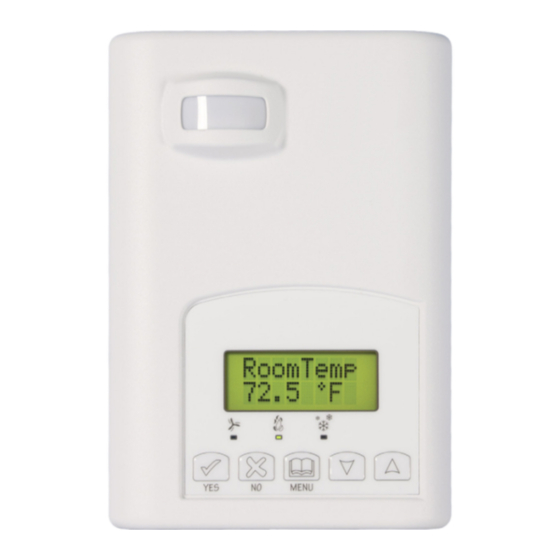
Page 8: Wiring Of Local Inputs To Vtr73Xxa Terminal Equipment Controller
If humidity display Sys mode Stand-By Network value only Filter enabled cool RoomTemp Sys mode Unoccup Window x.x °C or °F heat If humidity display Sys mode Override Low Batt is not enabled 8 | PIR Ready VTR7300 Series-Installation Guide... - Page 9 When any of the fan speeds are ON, the FAN LED will illuminate When heating & reheat is ON, the HEAT LED will illuminate When cooling is ON, the COOL LED will illuminate 9 | PIR Ready VTR7300 Series-Installation Guide...
-
Page 10: User Interface
Any setpoint change can be permanent or temporary based on configuration parameter (Setpoint Type) Any setpoint written through the network, will be permanent and cancel any active temporary setpoints Lockouts of access to certain functions is made with configuration parameter (lockout) 10 | PIR Ready VTR7300 Series-Installation Guide... -
Page 11: Dual Occupied Setpoints Adjustment
2 = Cooling / Heating Off – Auto – Heat – Cool Cooling With Electric Reheat 3 = Heating With Electric Reheat Off - Heat Off – Heat 4 = Electric Reheat Only 11 | PIR Ready VTR7300 Series-Installation Guide... -
Page 12: Installer Configuration Parameter Menu
To enter configuration, press and hold the middle button (°C/°F or Override) for 8 seconds. If a password lockout is active, “Password” is prompted. Enter password value using the “up” and “down” arrows and press the middle button again to gain 12 | PIR Ready VTR7300 Series-Installation Guide... -
Page 13: Configuration Interface
1 to 127. Default value of 254 disables BACnet™ communication for the Terminal Equipment Controller. For wireless models, the valid range is 0 to 254 with a maximum of 30 Terminal Equipment Controller per VWG 13 | PIR Ready VTR7300 Series-Installation Guide... - Page 14 Viconics recommends using only the usage of channels 15 and 25 only. The default value of 10 is NOT a valid channel. The valid range of available channel is from 11 to 26 14 | PIR Ready VTR7300 Series-Installation Guide...
- Page 15 Door/Window alarm displayed on the Terminal Equipment Controller to indicate to the local tenant that the door/window needs to be closed for cooling or heating to resume. Contact opened = Window Opened Contact closed = Window Closed 15 | PIR Ready VTR7300 Series-Installation Guide...
- Page 16 (Filter): A backlit flashing Filter alarm will be displayed on the Terminal Equipment Controller LCD screen when the input is energized. It can be tied to a differential pressure switch that monitor filters. 16 | PIR Ready VTR7300 Series-Installation Guide...
- Page 17 °F for Fahrenheit scale °C for Celsius scale Sets scale of the Terminal Equipment Controller On hotel models, this sets the default value when the Terminal Default value = °F Equipment Controller powers up 17 | PIR Ready VTR7300 Series-Installation Guide...
- Page 18 0 to 4 Default is: 4.0 Pipes Will enable heat/cool operation from the same output 4.0 Pipes, can access all the sequences of operation from 0 to 2 Will enable heat/cool operation from different output 18 | PIR Ready VTR7300 Series-Installation Guide...
- Page 19 Typically toggled via the network. On = Authorized This variable enables or disables dehumidification based on central network requirements from the BAS front end On = Dehumidification Authorized Off = Dehumidification Not Authorized 19 | PIR Ready VTR7300 Series-Installation Guide...
- Page 20 Default value = 78 °F can be recovered in a timely fashion when movement is detected in the zone. Stand-by cooling setpoint range is: 54 to 100 °F ( 12.0 to 37.5 °C ) 20 | PIR Ready VTR7300 Series-Installation Guide...
- Page 21 ° C SCALE VALUE ° F SCALE PBAND PBAND 1.2 C 1.7 C 2.2 C 2.8 C 3.3 C 3.9 C 5.0 C 10 F 5.6 C 21 | PIR Ready VTR7300 Series-Installation Guide...
- Page 22 0.0 °F or °C increments ) Cal RH Offset that can be added/subtracted to the actual displayed Humidity sensor humidity by ± 15.0 %RH. calibration Default value = 0 %RH Range is : ± 15.0 %RH 22 | PIR Ready VTR7300 Series-Installation Guide...
- Page 23 Off All; the controller in all cases will disable the fan (any terminals Low-Med—Hi Fan Speed). When the local fan mode is set to ANY mode. Valid in all fan sequences and all local fan modes 23 | PIR Ready VTR7300 Series-Installation Guide...
- Page 24 TO THE FOLLOWING TWO CONDITIONS: (1) THIS DEVICE MAY NOT CAUSE HARMFUL INTERFERENCE, AND (2) THIS DEVICE MUST ACCEPT ANY INTERFERENCE RECEIVED, INCLUDING INTERFERENCE THAT MAY CAUSE UNDESIRED OPERATION. Please check with your local government for instruction on disposal of this product 24 | PIR Ready VTR7300 Series-Installation Guide...
- Page 25 & D RAWING IMENSIONS Viconics Technologies Inc. Tel.: Fax: Toll free: www.viconics.com 25 | PIR Ready VTR7300 Series-Installation Guide...
Need help?
Do you have a question about the VTR7300 Series and is the answer not in the manual?
Questions and answers