Table of Contents
Advertisement
Quick Links
C
ONTENTS
Installation
Configuring and Status Display Instructions
1 | PIR Ready VT76xxW Series-Installation Guide
PIR Ready VT7600W Series
With & Without Local Schedule
Water Source Heat Pump
Terminal Equipment Controllers
Installation Guide
F o r C o m m e r c i a l H V AC Ap p l i c a t i o n s
r d
M a y 3
, 2 0 1 2 / 0 2 8 - 0 3 5 5 - R 4
2
2
2
3
3
5
5
6
6
7
7
7
8
11
12
13
13
14
15
22
32
32
34
35
Advertisement
Table of Contents

Related Manuals for Viconics VT7600W Series


Summary of Contents for Viconics VT7600W Series
-
Page 1: Table Of Contents
PIR Ready VT7600W Series With & Without Local Schedule Water Source Heat Pump Terminal Equipment Controllers Installation Guide F o r C o m m e r c i a l H V AC Ap p l i c a t i o n s... -
Page 2: Installation
NSTALLATION Remove the security screw on the bottom of Terminal Equipment Controller cover. Open unit by pulling on the bottom side of Terminal Equipment Controller (fig. 1). Remove wiring terminals from sticker. Please read the FCC ID and IC label installed in the cover upon removal of cover for the wireless products. -
Page 3: Theory Of Operation
HEORY OF OPERATION The VT7600 uses a Viconics proprietary adaptive logic algorithm to control the space temperature. This algorithm controls the heating / air conditioning system to minimize overshoot while still providing comfort. - Page 4 Remote discharge air temperature sensor input for monitoring purpose Remote water temperature sensor input for monitoring purpose Lockable keypads for tamper proofing. No need for a separate guards Anti short cycle and minimum on/off run time protection. Reduces wear and maximizes life span of mechanical equipment.
-
Page 5: Model Chart
ODEL HART Network ready All Viconics VT7600 series Terminal Equipment Controllers are designed for stand-alone operation. (Network Ready) They can be fully integrated into your choice of automation systems using the available communication adapter options. If required, stand-alone (Network Ready) Terminal Equipment Controllers can be field retrofitted with the following communication adapters: VCM7600N5000B, Terminal Equipment Controller BACnet™... -
Page 6: Terminal, Identification And Function
ERMINAL DENTIFICATION AND UNCTION Wiring Water Source Heat Pump Part Number VT7652W VT7600W Schedule Top left terminal block Top right terminal block Bottom terminal block Scom 6 | PIR Ready VT76xxW Series-Installation Guide... -
Page 7: Screw Terminal Arrangement
Screw terminal arrangement 2 pole left top connector 5 pole left top connector Y2 Y1 G RC C 7 pole bottom connector AU D1 D2 RS WS MS Scom Main outputs wiring Wiring notes: Note 1: Electromechanical contacts are to be used with the digital inputs. Electronic triacs cannot be used as mean of switching for the input. -
Page 8: Remote Sensor Accessories
Remote sensor accessories MODEL NO. DESCRIPTION S3010W1000 Wall mounted temperature sensor S3020W1000 Wall mounted temperature sensor+override button and occupancy status S2060A1000 Averaging temperature sensor S2000D1000 Duct mounted temperature sensor Remote mount temperature sensors use 10K NTC thermistor. This sensor can be used for: ... - Page 9 WIRING EXAMPLES OF 2 REMOTE ROOM SENSORS FOR AVERAGING APPLICATIONS: VT7600 Series 2x S3020W1000 2x S3010W1000 VT7600 Series Remote wiring 2 sensors Remote wiring 2 sensors S2-1 = OFF / S2-2 = ON S2-1 = OFF / S2-2 = S c o m S c o m S c o m S c o m...
- Page 10 -28 -18 151.6239 18 48.7042 54 17.9636 7.4182 52 126 3.3568 -27 -17 142.7211 19 46.1933 55 17.1440 7.1150 53 127 3.2333 -26 -15 134.3971 21 43.8268 57 16.3665 6.8259 54 129 3.1150 -25 -13 126.6109 23 41.5956 59 15.6286 6.5499 55 131 3.0016...
-
Page 11: Status Display
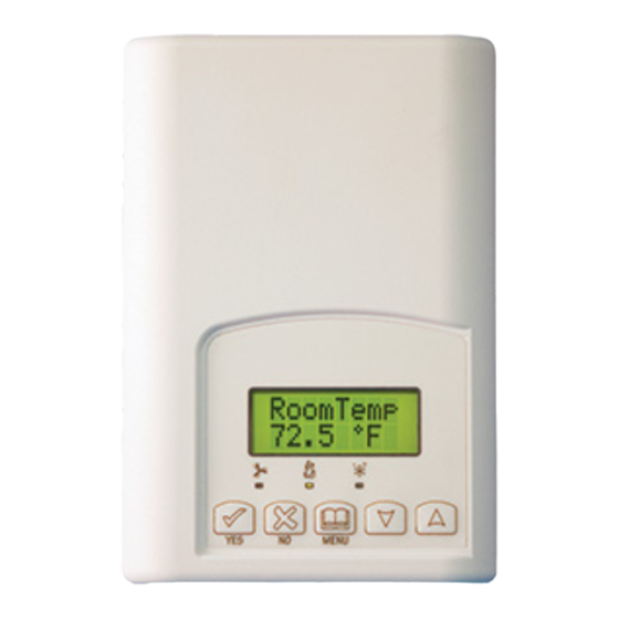
WIRING S2000D1000, S2060A1000 AND S2020E1000 Remote wiring 1 sensor Remote wiring 4 sensors 10 K 10 K 10 K 10 K 10 K Scom Scom Scom Scom Scom Scom User menu flow chart: NOTE: Prompts may not all be present depending on model selected If status is: Override MENU... - Page 12 Status display The Terminal Equipment Controller features a two-line, eight-character display. There is a low level backlight level that is always active and can only be seen at night. When left unattended, the Terminal Equipment Controller has an auto scrolling display that shows the actual status of the system.
-
Page 13: User Interface
Indicates that the heating is energized by the low limit frost protection room Frost ON temperature setpoint 5.6 °C ( 42 °F ) Indicates that the clock needs to be reset. There has been a power failure SetClock which has lasted longer than 6 hours Indicates that there is a service alarm as per one of the configurable digital Service input ( DI1 or DI2 ) -
Page 14: Local Keypad Interface
If the user pauses at any given time during configuring, Auto Help text is displayed to help and guide the user through the usage and configuring of the Terminal Equipment Controller. Press yes key to change cooling temperature setpoint Ex.: Use the up or down arrow to adjust cooling setpoint Local keypad interface Each of the sections in the menu is accessed and configured using 5 keys on the... -
Page 15: Occupied Setpoints Adjustments
Sequence of user menu: SYSTEM OVERRIDE TEMPERATURE SCHEDULES CLOCK SCHEDULE MODE MODE RESUME SETPOINTS SETTING SETTING HOLD SETTING SETTING Override Temperat mode Schedule Clock Schedule mode schd Y/N Set Y/N set Y/N set Y/N hold Y/N set Y/N Appears Appears only on only in stand-alone... - Page 16 A) Override an unoccupied period Override schd Y/N This menu will appear only when the Terminal Equipment Controller is in unoccupied mode. The unoccupied mode is enabled either by the internal timer scheduling or by a remote NSB contact via DI1 or DI2. If DI1 or DI2 is configured to operate as a remote temporary override contact, this menu will be disabled.
- Page 17 Local changes to the heating or cooling setpoints made by the user directly using the up or down arrow are temporary. They will remain effective for the duration specified by ToccTime. Setpoints will revert back to their default value after internal timer ToccTime expires. If a permanent change to the setpoints is required, use the Temperat set ? menu D) System mode setting Sys mode...
- Page 18 F) Schedule set (2 events) Scheduling can have 2 or 4 events per day. This is set in the configuration menu as per parameter (2/4event) Schedule This section of the menu permits the user to set the whether 2 or 4 events is needed. Each day can be tailored to specific schedules if needed.
- Page 19 Ex. #2 Commercial building which is occupied all weekend Period #1 - Event Period #1 - Event Event Occupied Unoccupied Cool Heat Cool Heat Daily Setpoint Occupancy 72 °F 70 °F 80 °F 62 °F Monday 8.00 AM 5.00 PM Day time only Tuesday 8.00 AM...
- Page 20 Ex. #1 Four event retail establishment schedule Period 1 - Period 1 - Period 2 - Period 2 - Event Event 1 Event 2 Event 3 Event 4 Setpoint Occupied Unoccupied Occupied Unoccupied Cool Heat Cool Heat Cool Heat Cool Heat Daily Occupancy...
- Page 21 H) Clock/Day Settings Clock This section of the menu permits the user to set the time and day. Time setting Day setting Time format setting No next No next Time 12/24hrs No = exit Yes down Yes down Yes down ...
-
Page 22: Installer Configuration Parameter Menu
Schedule uno hold Hold permanent unoccupied forces the Terminal Equipment Controller into a permanent unoccupied mode using the unoccupied setpoints. All timed scheduling functions are by-passed. The PERMANENT UNOCCUPIED status will appear in the automatic status scroll. To resume to regular scheduling, user must scroll to the Schedule Hold menu and select the Schedule resume option. - Page 23 This parameter (Personal Area Network Identification) is used to link specific Terminal Equipment Controllers to a single specific Viconics wireless gateway ( VWG ) For every Terminal Equipment Controller reporting to a gateway ( maximum of 30 Terminal Equipment Controllers per...
- Page 24 SAME channel value both at the gateway and the Terminal Equipment Controller(s). Viconics recommends using only the usage of channels 15 and 25 only. The default value of 10 is NOT a valid channel. The...
- Page 25 DI 1 (None) : No function will be associated with the input Digital input no.1 (Rem NSB): remote NSB timer clock input. Will disable the configuration internal scheduling of the Terminal Equipment Controller. The scheduling will now be set as per the digital input. The time is Open contact input = still displayed as information, but the menu part related to function not energized...
- Page 26 lockout Keypad lockout levels 0 = No lock 1 = Low level Default value = 0 No lock 2 = High level USER KEY FUNCTIONS pwr del On initial power up of the Terminal Equipment Controller (each time 24 Vac power supply is removed & re-applied) Power-up delay there is a delay before any operation is authorized (fan, cooling or heating).
- Page 27 Pband Adjust the proportional band used by the Terminal Equipment Proportional Band Controller PI control loop. setting Default value 2 = 2.0 Note that the default value of 2.0 °F ( 1.1 °C ) gives °F ( 0.6 °C ) satisfactory operation in most normal installation cases.
- Page 28 deadband Minimum deadband value between the heating and cooling Minimum deadband setpoints. If modified, it will be applied only when any of the Default value = 2.0 °F setpoints are modified. ( 1.1 °C ) 2, 3 or 4 °F ( 1.0 to 2.0 °C ) fan cont Fan control in heating mode.
- Page 29 HP stage Will revert the operation of 2 stage Terminal Equipment Number of heatpump Controller to single stage operation only when the second stages compressor step is not needed. Default value = 2 stages 1 or 2 stages H lock Disables heating stage operation based on outdoor air Outside air temperature temperature.
- Page 30 aux cont This contact can be used to energize peripheral devices such Auxiliary contact as: lighting equipment, exhaust fans, economizers, etc. configuration This contact will operate in parallel with the internal Default value = N.O. occupied/unoccupied schedule of the Terminal Equipment normally open Controller or the remote NSB contact if DI1 or DI2 is used.
- Page 31 Dhu set Used only if dehumidification sequence is enabled: Dehumidification setpoint Default is 50 % RH Range is: 30-95% RH DHumiLCK Enables, restricts or disables the dehumidification sequence. Dehumidification lockout Default value: Dhu Disa: Dehumidification disabled Restrict Restrict: will restrict the dehumidification process based on the following: System mode = Needs to be Cool or Auto ( currently operating in cooling only )
-
Page 32: Troubleshooting Guide
ROUBLESHOOTING GUIDE All models Symptom Possible Cause Corrective Action 1. Check power supply voltage between C Absent or incorrect & RC to be from 19-30 VAC supply voltage No display on the 2. Check for tripped fuse or circuit breaker Terminal Verify that the transformer used is Equipment... - Page 33 1. Start the Fan by forcing the Fan ON mode Wiring error 2. Put a jumper across terminals RC & Y1. The cooling should come ON. If it does not, verify wiring Wrong mode selected 1. Start the Fan by forcing the Fan ON The Terminal mode Equipment...
-
Page 34: Specifications
PECIFICATIONS Terminal Equipment Controller power requirements: 19-30 VAC 50 or 60 Hz; 2 VA Class 2 Operating conditions: 0 °C to 50 °C ( 32 °F to 122 °F ) 0% to 95% R.H. non-condensing Storage conditions: -30 °C to 50 °C ( -22 °F to 122 °F ) 0% to 95% R.H. -
Page 35: Drawing & Dimensions
& D RAWING IMENSIONS Viconics Technologies Inc. Tel.: Fax: Toll free: www.viconics.com 35 | PIR Ready VT76xxW Series-Installation Guide...
Need help?
Do you have a question about the VT7600W Series and is the answer not in the manual?
Questions and answers