Table of Contents
Advertisement
C
ONTENTS
Installation
Installation
1 | PIR Ready VT7200 Series-Installation Guide
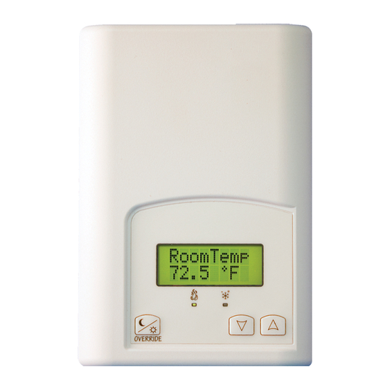
PIR Ready VT7200 Series 24 VAC Low Voltage
Zoning Terminal Equipment Controller
Installation Guide
F o r C o m m e r c i a l H V A C A p p l i c a t i o n s
M a y 3
2
2
2
3
5
6
6
7
7
8
12
13
13
15
15
16
16
16
16
16
17
28
29
Advertisement
Table of Contents

Related Manuals for Viconics VT7200 F 5000 B


Summary of Contents for Viconics VT7200 F 5000 B
-
Page 1: Table Of Contents
PIR Ready VT7200 Series 24 VAC Low Voltage Zoning Terminal Equipment Controller Installation Guide F o r C o m m e r c i a l H V A C A p p l i c a t i o n s M a y 3 , 2 0 1 2 / 0 2 8 - 0 1 9 0 - R 8 ONTENTS... -
Page 2: Location
NSTALLATION Remove the security screw on the bottom of Terminal Equipment Controller cover. Open unit by pulling on the bottom side of Terminal Equipment Controller (fig. Remove wiring terminals from sticker. Please read the FCC ID and IC label installed in the cover upon removal of cover for the wireless products. -
Page 3: M A Y 3 R D , 2 0 1 2 / 0 2 8 - 0 1 9 0 - R
13. Re-install the cover (top side first) and gently push extra wire length back into the hole in the wall. 14. Install security screw. If replacing an existing Terminal Equipment Controller, label the wires before removal of the Terminal Equipment Controller. ... - Page 4 Binary input #2 can be configured for the following functions: (None): No function will be associated with the input (Door Dry) Door contact & Motion detector: This configuration is only functional if binary input #1 is set to Motion NO or Motion NC or a PIR accessory cover is used.
-
Page 5: Model Chart
(COS) Change over analog sensor: Used for hot / cold air / water change over switching in 2 pipe systems. Only used and valid if system is setup as 2.0. Parameter ( Out1Conf ) set as 2.0. If temperature is > 77 °F = Hot air / water present If temperature is <... -
Page 6: Network Ready
Network ready All Viconics VT7200 series Terminal Equipment Controllers are designed for stand-alone (Network Ready) operation. They can be fully integrated into your choice of automation systems using the available communication adapter options. If required, stand-alone (Network Ready) Terminal Equipment Controllers can be field retrofitted with the following communication adapters: VCM7300V5000B, Terminal Equipment Controller BACnet™... -
Page 7: Wiring
Wiring Remote inputs ( All models ) Contact SS ( supply sensor ) BI 1 - Rem NSB - S1010E1000 Remote wall sensor - Motion - S2000D1000 - S3010W1000 - Window COS ( changeover sensor ) - S3020W1000 Scom - S1010E1000 BI 2 UI 3 COC/NH... -
Page 8: Typical Applications
Analog control VT7200F5x00(x) 24 V~ Hot 24 V~ Hot 24 V~ Com 24 V~ Com Heating valve 24 VAC AO 2 Heating / Cooling valve 0-10 VDC Cooling valve 24 VAC 24 VAC AO 1 AO 1 0-10 VDC 0-10 VDC Typical applications Schematic Wiring... - Page 9 Pressure dependent VAV cooling / heating with changeover: VT7200C5x00(x) Floating actuator Mandatory Changeover Modulating Floating Out1Conf = 2.0 Supply air Sensor VAV Actuator temperature sensor CntrltTyp = Floating FL time = as per actuator If heat / cool auto- UI3 COS changeover with a local 0 V~ Com...
- Page 10 Pressure dependent VAV cooling / heating with changeover and reheat: VT7200C5x00(x) Floating actuator Mandatory Modulating Floating Out1Conf = 2.0 VAV Actuator Supply air CntrltTyp = Floating Heating and/or Cooling temperature sensor & On/Off Duct Heater FL time = as per actuator If heat / cool auto- UI3 COS...
- Page 11 Schematic Wiring Settings Heating or cooling hydronic valve control: VT7200C5x00(x) Floating actuator Mandatory Modulating Floating Out1Conf = 2.0 Valve Cooling or Heating CntrltTyp = Floating UI3 COS FL time = as per 0 V~ Com actuator 24 V~ Hot BO1 Open If cooling only set:: BO2 Close...
-
Page 12: Remote Sensor Accessories
Cooling / heating with changeover hydronic valve control: VT7200F5x00(x) Analog actuator Mandatory Analog Valve Out1Conf = 2.0 Heating and/or Cooling RA/DA = as per UI3 COS actuator 0 V~ Com 24 V~ Hot Optional Water If heat / cool auto- Supply Sensor changeover with a local 0 to 10... -
Page 13: Configuring And Status Display Instructions
Wiring examples of 2 remote room sensors for averaging applications: VT7200 Series 1 x S3010W1000 and 1 x S3020W1000 2 x S3020W1000 VT7200 Series Remote wiring 2 sensors Remote wiring 2 sensors S1=On, S2=Off S2=On, S3=Off Scom Scom Scom Scom Scom Scom Scom... - Page 14 seconds after changes are made, the display will resume automatic status display scrolling. To turn on the back light to high level, press any key on the front panel. The back lit display will return to low level when the Terminal Equipment Controller is left unattended for 45 seconds Sequence of auto-scroll status display: ROOM &...
-
Page 15: User Interface
Zoning Models When heating & reheat is ON, the HEAT LED will illuminate When cooling is ON, the COOL LED will illuminate NTERFACE Unoccupied mode override An Override can be made during an unoccupied period. If the Override option is enabled in the lockout configuration pressing the Override button will resume occupied setpoints for a time specified by parameter ToccTime Local keypad interface... -
Page 16: Occupied Setpoints Adjustments
Occupied setpoints adjustments AUTO MODE Setpoint presented to user is the setpoint from the last action taken by the Terminal Equipment Controller or the one currently in COOLING HEATING use. MODE MODE MODE Both heating and cooling setpoints are changed simultaneously while respecting the minimum configured deadband Heat... -
Page 17: Configuration Interface
access to all configuration properties of the Terminal Equipment Controller. Entering a wrong password will prevent local access to the configuration menu. Press the same middle button repetitively to scroll between all the available parameters. Use the up and down key to change the parameter to the desired value. ... - Page 18 This parameter (Personal Area Network Identification) is used to link specific Terminal Equipment Controllers to a single specific Viconics wireless gateway ( VWG ). For every Terminal Equipment Controller reporting to a gateway ( maximum of 30...
- Page 19 Get From Conditional parameter to Wireless models Terminal Equipment (VT7200X5x00W) Controller Get From another device Entering a MAC address enables an automatic routine that configuration utility automatically fetches all the required configuration properties Default value = 0 of the current device from another already configured device Range is: 0 to 254 and copies the same required configured property values.
- Page 20 BI 1 (None): No function will be associated with the input. Input can Binary input no.1 be used for remote network monitoring. configuration Default value = None (Rem NSB): remote NSB timer clock input. The scheduling will now be set as per the binary input. It provides low cost setback operation via a dry contact ...
- Page 21 (Filter): a backlit flashing Filter alarm will be displayed on the Terminal Equipment Controller LCD screen when the input is energized. It can be tied to a differential pressure switch that monitor filters Contact opened = No alarm ...
- Page 22 Lockout Keypad lockout levels Default value = 0 No lock USER KEY FUNCTIONS LEVEL NOT USED Out1Conf Defines the type of operation needed for Output #1 (BO1 Output # 1 configuration & BO2) Default is: 4.0 (2 control 2.0, will limit the number of sequences of operation outputs, no changeover) available from 0 to 3 Will enable heat/cool operation from the same output...
- Page 23 Time delay between the moment where the PIR cover St-By TM detected the last movement in the area and the time which Stand-by Timer value the Terminal Equipment Controller stand-by mode and Default 0.5 hours setpoints become active. Range is: 0.5 to 24.0 hours in 0.5hr increments Time delay between the moment where the Terminal Unocc TM Equipment Controller toggles to stand-by mode and the time...
- Page 24 Pband Adjust the proportional band used by the Terminal Equipment Proportional band setting Controller PI control loop. Default is : 3 Note that the default value of 3.0 °F (1.2 °C) gives satisfactory operation in most normal installation cases. The use of a proportional band different than the factory one is normally warranted in applications where the Terminal Equipment Controller location is problematic and leads to...
- Page 25 Set Type Temporar: (temporary) Local changes to the heating or cooling Temporary setpoint setpoints by the user are temporary. They will remain effective for the duration specified by “ToccTime”. Setpoints will then enable revert back to their default value after internal timer “ToccTime” Default is : Permnent expires.
- Page 26 aux cont 0 Aux contact function used for reheat Auxiliary contact function IF SEQUENCE IS SET TO REHEAT THROUGH NETWORK & configuration OR LOCAL, Ignore this parameter Default value = 0 Not Used The output will directly follow the occupancy of the Terminal Equipment Controller 1 Auxiliary NO, Occ or St-By = Contact Closed / Unoccupied = Contact Opened...
- Page 27 RA/DA Changes the action of the analog outputs on the analog Reverse acting or Direct models. acting signal for Analog DA = Direct acting output signals 0 to 100 % = 0 to 10 VDC VT72xxF5x00(x) models RA = Reverse acting only 0 to 10 % - 10 to 0 VDC Default value: DA signal...
-
Page 28: Specifications
PECIFICATIONS Terminal Equipment Controller power requirements: 19-30 VAC 50 or 60 Hz; 2 VA Class 2 Operating conditions: 0 °C to 50 °C ( 32 °F to 122 °F ) 0% to 95% R.H. non-condensing Storage conditions: -30 °C to 50 °C ( -22 °F to 122 °F ) 0% to 95% R.H. -
Page 29: Drawing & Dimensions
& D RAWING IMENSIONS Viconics Technologies Inc. Tel.: Fax: Toll free: www.viconics.com 29 | PIR Ready VT7200 Series-Installation Guide...
Need help?
Do you have a question about the VT7200 F 5000 B and is the answer not in the manual?
Questions and answers