Viconics VT8000 Series Installation Manual
Low voltage (24vac) fan coil unit (fcu) and zone control
Hide thumbs
Also See for VT8000 Series:
- User manual (85 pages) ,
- User interface manual (82 pages) ,
- Installation & quick start manual (19 pages)

Related Manuals for Viconics VT8000 Series


Summary of Contents for Viconics VT8000 Series
- Page 1 VT8000 Room Controllers VT8350 Installation Guide Low Voltage (24VAC) Fan Coil Unit (FCU) and Zone Control Version 12...
-
Page 2: Table Of Contents
TABLE OF CONTENTS SAFETY INFORMATION ..........................3 INSTALLATION .............................. 6 TERMINAL IDENTIFICATION AND FUNCTION ..................... 7 HOME SCREEN DISPLAY ........................... 12 HOW TO ENTER SET-UP SCREEN ......................13 SET-UP SCREEN DISPLAY .......................... 13 APPENDIX A. TERMINAL CORRESPONDENCE ................... 14 APPENDIX B. POWER OUTAGE CLOCK RESET ................... -
Page 3: Safety Information
Electrical equipment should be installed, operated, serviced, and maintained only by qualified personnel. No responsibility is assumed by Viconics Technologies for any consequences arising out of the use of this material. A qualified person is one who has skills and knowledge related to the construction, installation, and operation of electrical equipment and has received safety training to recognize and avoid the hazards involved. - Page 4 Avoid touching exposed conductors and components leads with skin or clothing. For additional information about anticipated transmission delays or failures of the link, refer to NEMA ICS 1.1 (latest edition), Safety Guidelines for the Application , Installation, and Maintenance of Solid State Control or its equivalent 028-0429-12_II-VT8350_EN www.viconics.com February 2020...
- Page 5 • Do not drop or crush the Room Controller, or allow it to come into contact with liquids. • Do not use a damaged device (such as one with a cracked screen). Failure to comply with these recommendations will result in damage to the unit and void the manufacturer’s warranty. 028-0429-12_II-VT8350_EN www.viconics.com February 2020...
-
Page 6: Installation
12. Gently push excess wiring back into the hole. 13. Gently align the cover with the top of the base and snap it into place from the bottom (Figure 3). 14. Install the security screw (if applicable). Figure-3 Reinstall cover 028-0429-12_II-VT8350_EN www.viconics.com February 2020... -
Page 7: Terminal Identification And Function
16- UI16 UI16 Function 17- UI17 UI17 Function 18- Scom Common 19- UI19 UI19 Function 20- UI20 Remote Room Sensor 21- Scom Common 22- UI22 Remote Supply Sensor 23- UI23 Not used 24- UI24 Not used 028-0429-12_II-VT8350_EN www.viconics.com February 2020... - Page 8 RS485 Ref 16- UI16 UI16 Function 17- UI17 UI17 Function 18-Scom Common 19- UI19 UI19 Function 20- UI20 Remote Room Sensor 21-Scom Common 22- UI22 Remote Supply Sensor 23- UI23 Not used 24- UI24 Not used 028-0429-12_II-VT8350_EN www.viconics.com February 2020...
- Page 9 BO8 - Aux Heat BO8 - Aux Heat Wiring ECM Motor Relay Coil 24Vac 24Vac signal to start fan (optional) BO4 - Fan H Transformer RC (24 Vac) C (Common) 0 - 10Vdc signal UO10 ECM Fan 028-0429-12_II-VT8350_EN www.viconics.com February 2020...
- Page 10 Disconnecting the sensor(s) in the RS terminal will re-activate the internal sensor. Features: Each sensor can be configured for various averaging combinations (refer to S3000 remote sensors for more details) • Optional occupancy led • Optional override key 028-0429-12_II-VT8350_EN www.viconics.com February 2020...
- Page 11 ºF Kohm -40 324.3197 -20 -4 94.5149 32.1910 68 12.4601 5.3467 -31 234.4009 -15 5 71.2430 25.1119 77 10.0000 4.3881 -22 171.3474 -10 14 54.1988 19.7390 86 8.0694 3.6202 -13 126.6109 41.5956 15.6286 95 6.5499 3.0016 028-0429-12_II-VT8350_EN www.viconics.com February 2020...
-
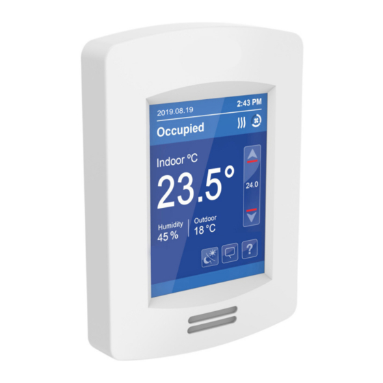
Page 12: Home Screen Display
Short Network Message Language Selection Fan Mode Temperature Units NOTE: User HMI is configurable and allows display functions such as Date, Time, Humidity, Outdoor Temperature, Setpoint, and others to be enabled or disabled by setting various parameters. 028-0429-12_II-VT8350_EN www.viconics.com February 2020... -
Page 13: How To Enter Set-Up Screen
Di sp lay Enter display settings Enter status display (read only) S ervi ce v i ew Enter test outputs settings Test O utp ut s General Note: Adjustable parameter Return to home screen Nonadjustable parameter 028-0429-12_II-VT8350_EN www.viconics.com February 2020... -
Page 14: Appendix A. Terminal Correspondence
36 - 72 hours Clock no longer increments and will need to be adjusted when power is restored. 72+ hours Clock functions are fully reset, and will need to be reinitialized as per a new installation. 028-0429-12_II-VT8350_EN www.viconics.com February 2020... -
Page 15: Appendix C. Deployment
Moreover, for each case aforementioned, occupant movement almost always moves lateral to the PIR, which ensures detection by the PIR, as well as respecting the PIR detection range of 20 feet (6 meters) at 140°, and 16 feet (5 meters) between 15° to 30° laterally. Recommended Installation 028-0429-12_II-VT8350_EN www.viconics.com February 2020... - Page 16 PIR would get blocked, and therefore, occupancy going undetected. For the Room Controller installed beside the reception area, occupant traffic could fall outside the detection zone, and the receptionist would often be below the 5 foot recommended installation height for the Room Controller. Non-Recommended Installation 028-0429-12_II-VT8350_EN www.viconics.com February 2020...
- Page 17 (guest is sleeping) More aggressive energy savings logic but may cause bad guest Good energy savings logic and better guest experience even when the experience (when guest is sleeping or not moving) guest is sleeping or not moving 028-0429-12_II-VT8350_EN www.viconics.com February 2020...
- Page 18 PIR can maximize your energy saving from 10-30% by adjusting temperature set points in unoccupied zones during scheduled periods. Typical Savings of 10-30% PIR can maximize your energy saving from 10-30% by adjusting temperature set points in unoccupied zones during scheduled periods. Time of Day (EST) Typical Consumption PIR Thermostat Consumption Savings 028-0429-12_II-VT8350_EN www.viconics.com February 2020...
Need help?
Do you have a question about the VT8000 Series and is the answer not in the manual?
Questions and answers