
Subscribe to Our Youtube Channel
Related Manuals for Viconics VT7200 Series


Summary of Contents for Viconics VT7200 Series
-
Page 1: Table Of Contents
VT7200 Series Installation Guide F o r C o m m e r c i a l H V A C A p p l i c a t i o n s N o ve m b e r 2 0 1 5... -
Page 2: Installation
NSTALLATION Remove security screw on bottom of Room Controller cover. Open unit by pulling on bottom side of Room Controller (fig. 1). Remove wiring terminals from sticker. Read FCC ID and IC label installed in the cover. Location Should not be installed on outside wall. -
Page 3: Configurable Bi/Ui Inputs Overview
If replacing an existing Room Controller, label the wires before removal of the Room Controller. Electronic controls are static sensitive devices. Discharge yourself properly before manipulating and installing the Room Controller. A short circuit or wrong wiring may permanently damage the Room Controller or the equipment. - Page 4 Binary input #2 can be configured for the following functions: (None): No function will be associated with the input (Door Dry) Door contact & Motion detector: This configuration is only functional if binary input #1 is set to Motion NO or Motion NC or a PIR accessory cover is used.
-
Page 5: Network Ready
Only used for network reporting of the supply air temperature. Has no internal function in the Room Controller. Network ready All Viconics VT7200 series Room Controllers are designed for stand-alone (Network Ready) operation. They can be fully integrated into your choice of automation systems using the available communication adapter options. -
Page 6: Wiring
Wiring Remote inputs (All models) Contact SS (supply sensor) BI 1 - Rem NSB - S1010E1000 Remote wall sensor - Motion - S2000D1000 - S3010W1000 - Window COS (changeover sensor) - S3020W1000 Scom - S1010E1000 BI 2 UI 3 COC/NH Contact - Door - Normally heat... -
Page 7: Typical Applications
Analog control VT7200F5x00(x) 24 V~ Hot 24 V~ Com Heating / Cooling valve 24 VAC AO 1 0-10 VDC Typical applications Schematic Wiring Settings Pressure dependent VAV cooling only:VT7200C5x00(x) Floating actuator Mandatory Modulating Floating Out1Conf = 2.0 VAV Actuator ... - Page 8 Pressure dependent VAV cooling / heating with changeover: VT7200C5x00(x) Floating actuator Mandatory Changeover Modulating Floating Out1Conf = 2.0 Sensor VAV Actuator CntrltTyp = Floating FL time = as per actuator If heat / cool auto- changeover with a Room Temperature Control local discharge air Minimum...
- Page 9 Pressure dependent VAV cooling / heating with changeover and reheat: VT7200C5x00(x) Floating actuator Mandatory Modulating Floating Out1Conf = 2.0 VAV Actuator Supply air CntrltTyp = Heating and/or Cooling temperature sensor Floating & On/Off Duct Heater FL time = as per actuator UI3 COS If heat / cool auto-...
- Page 10 Schematic Wiring Settings Heating or cooling hydronic valve control: VT7200C5x00(x) Floating actuator Mandatory Modulating Floating Out1Conf = 2.0 Valve Cooling or Heating CntrltTyp = Floating FL time = as per actuator If cooling only set:: SeqOpera = 0 Cooling only Room Temperature Control Thermostat...
- Page 11 Cooling / heating with changeover hydronic valve control: VT7200F5x00(x) Analog actuator Mandatory Analog Valve Out1Conf = 2.0 Heating and/or Cooling RA/DA = as per UI3 COS actuator 0 V~ Com 24 V~ Hot Optional Water If heat / cool auto- Supply Sensor changeover with a 0 to 10...
- Page 12 Optional override key S3020W1000 Wall mounted sensor Wiring example of single remote room sensor: S3010W1000 VT7200 Series S3020W1000 Remote wiring 1 sensor Remote wiring 1 sensor S2=On, S3=On S2=On, S3=On S2 – 1 = ON, S2 – 2 = ON S2 –...
- Page 13 Wiring examples of 2 remote room sensors for averaging applications: VT7200 Series 1 x S3010W1000 and 1 x S3020W1000 2 x S3020W1000 VT7200 Series Remote wiring 2 sensors Remote wiring 2 sensors S1=On, S2=Off S2=On, S3=Off S2 – 1 = ON, S2 – 2 = OFF S2 –...
-
Page 14: Configuring And Status Display Instructions
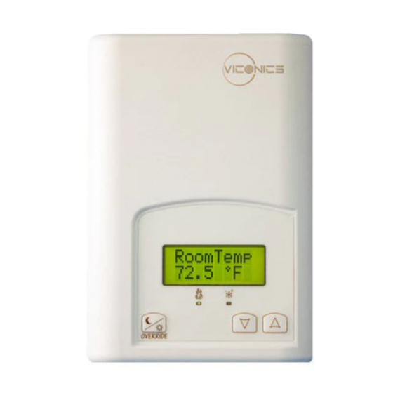
ONFIGURING AND TATUS ISPLAY NSTRUCTIONS Status display The Room Controller features a two-line, eight-character display. There is a low level backlight level that is always active and can only be seen at night. When left unattended, the Room Controller has an auto scrolling display that shows the actual status of the system. - Page 15 Two status LED’s on the Room Control cover are used to indicate a call for heat or a call for cooling. Zoning Models When heating & reheat is ON, the HEAT LED will illuminate When cooling is ON, the COOL LED will illuminate 15 | 028-0190-09 November 2015...
-
Page 16: User Interface
NTERFACE Unoccupied mode override An Override can be made during an unoccupied period. If the Override option is enabled in the lockout configuration pressing the Override button will resume occupied setpoints for a time specified by parameter ToccTime Local keypad interface ... - Page 17 Viconics Technologies Inc. Tel.: Fax: Toll free: www.viconics.com 17 | 028-0190-09 November 2015...
Need help?
Do you have a question about the VT7200 Series and is the answer not in the manual?
Questions and answers