Advertisement
Features
•
0 to 10 VDC modulating output
•
VDC pulsed modulating output
•
VAC pulsed modulating output
•
Night setback digital input
•
Room or supply control applications
Description
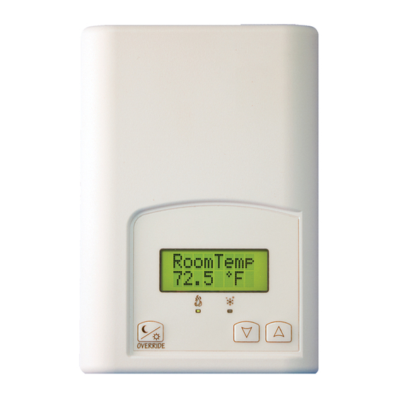
The VT7225 series controllers are microcomputer-based, proportional and
integral (PI) devices with one analog 0 to 10 Vdc output, one 8 Vdc and one 24
Vac proportioning pulsed output.
The analog 0 to 10 Vdc modulating output can control the room or supply
temperature by modulating directly a 0 to 10 Vdc SCR power controller.
The Vdc and Vac pulsed outputs can control the room or supply temperature by
modulating directly 4-32 Vdc triggered solid state relays (SSR's) using a time
proportioning control algorithm on a 1 second time cycle.
1 | 028-0485-00
Installation Guide
F o r M o d u l a t i n g E l e c t r i c H e a t A p p l i c a t i o n s
VT7225 Series
N o ve m b e r 2 0 1 7
November 2017
Advertisement

Related Manuals for Viconics VT7225 series


Summary of Contents for Viconics VT7225 series
- Page 1 • Room or supply control applications Description The VT7225 series controllers are microcomputer-based, proportional and integral (PI) devices with one analog 0 to 10 Vdc output, one 8 Vdc and one 24 Vac proportioning pulsed output. The analog 0 to 10 Vdc modulating output can control the room or supply temperature by modulating directly a 0 to 10 Vdc SCR power controller.
-
Page 2: Table Of Contents
ONTENTS Installation Location Installation BI 1 UI 3 Terminal Identification and Function Output Types Wiring Remote sensor accessories 2 | 028-0485-00 November 2017... -
Page 3: Installation
NSTALLATION Remove security screw on bottom of Room Controller cover. ▪ Open unit by pulling on bottom side of Room Controller (fig. 1). ▪ Remove wiring terminals from sticker. ▪ Read FCC ID and IC label installed in the cover. Location Do not install on outside wall. - Page 4 ▪ If replacing an existing Room Controller, label the wires before removal of the Room Controller. ▪ Electronic controls are static sensitive devices. Discharge yourself properly before manipulating and installing the Room Controller. ▪ A short circuit or wrong wiring may permanently damage the Room Controller or the equipment.
-
Page 5: Terminal Identification And Function
BI 1 Binary input #1 function: Remote NSB timer clock input. The scheduling will now be set as per the binary input. It provides low cost setback operation via a dry contact: • Contact opened = Occupied • Contact closed = Unoccupied UI 3 Supply air sensor: Used for supply air temperature control. -
Page 6: Output Types
Output Types Type of Output Controlled Device SCR’s power controls Modulating analog 0 to 10 Vdc output 4-32 Vdc triggered SSR’s Vdc pulsed output 24 Vac triggered SSR’s Vac pulsed output 6 | 028-0485-00 November 2017... -
Page 7: Wiring
Wiring Supply temperature control with 0 to 10Vdc SCR and override input Return temperature control with 0 to 10Vdc SCR By closing contact on BI 1, will force setpoint to « Unocc HT » adjustable inside setup parameters. By adjusting to a low setpoint (ex: 0°F) is a way to disable heating. - Page 8 Room temperature control with 4-32Vdc SSR Room temperature control with 4-32Vdc SSR Up to 4x 4-32Vdc SSR Up to 4x (see wiring detail) 4-32Vdc SSR (see wiring detail) 24V~ BI 1 24V~ 24V~ BI 1 24V~ AO 2 AO 1 AO 2 AO 1 Wiring detail for 4x 4-32 Vdc SSR...
- Page 9 Room remote temperature control with 4-32Vdc SSR 1x, 2x or 3x remote sensors for averaging room temperature reading (see S3010W1000 manual for proper settings) 24V~ BI 1 24V~ AO 2 AO 1 9 | 028-0485-00 November 2017...
- Page 10 Room temperature control with 24 Vac SSR Up to 10x 24Vac SSR (see wiring detail) 24V~ BI 1 24V~ AO 2 AO 1 Up to 10x 24Vac SSR in parallel (or add C24 adapter board to regular 3-32Vdc SSR) Wiring details 24V~ BI 1 24V~...
-
Page 11: Remote Sensor Accessories
Remote sensor accessories Model Description Application Picture • Remote sensing easy to dissimulate for Capsule type sensor for indoor and outdoor multipurpose use, ¼” dia. capsule S1010E1000 • with Water temperature 65 inch leads sensing strapped on pipe or in an immersion well •... - Page 12 0 to 10 Vdc into 2Kohm resistance min. • 5 mA max at 10 Vdc Vdc pulsed output 20 mA max at 8 Vdc Power 24 Vac -15%, +10% 50/60 Hz; 2 Va Viconics Technologies Inc. Tel.: Fax: Toll free: www.viconics.com 12 | 028-0485-00 November 2017...
Need help?
Do you have a question about the VT7225 series and is the answer not in the manual?
Questions and answers