
Related Manuals for Nidec Digitax HD M75X Series


Summary of Contents for Nidec Digitax HD M75X Series
- Page 1 Quick Start Guide Digitax HD M75X Series Variable speed AC drive for Servo and Induction motors Part Number: 0478-0500-02 Issue: 2...
- Page 2 This guide does not include safety information. Incorrect installation or operation of the drive, could cause personnel injury or equipment damage. For essential safety information, please refer to the relevant drive documentation or safety booklet supplied with the drive. WARNING Copyright © May 2018 Nidec Control Techniques Ltd. Issue Number: 2...
-
Page 3: Table Of Contents
Contents Product information ..................8 Ratings ........................8 Model number ......................8 Drive features ......................9 Mechanical installation ................10 Electrical installation .................11 AC supply requirements ..................11 DC supply requirements ..................11 External 24 Vdc supply ..................11 Terminal size and torque settings ................12 Getting started ...................13 Display and Keypad operation ................ - Page 4 EU Declaration of Conformity Nidec Control Techniques Ltd The Gro Newtown Powys SY16 3BE This declaration is issued under the sole responsibility of the manufacturer. The object of the declaration is in conformity with the relevant European Union harmonization legislation.
- Page 5 These products comply with the Restriction of Hazardous Substances Directive (2011/65/EU), the Low Voltage Directive (2014/35/EU) and the Electromagnetic Compatibility Directive (2014/30/EU). Jonathan Holman-White Director, Technology Date: 14th May 2018 Place: Newtown, Powys, UK These electronic drive products are intended to be used with appropriate motors, controllers, electrical protection components and other equipment to form complete end products or systems.
- Page 6 EU Declaration of Conformity (including 2006 Machinery Directive) Nidec Control Techniques Ltd The Gro Newtown Powys SY16 3BE This declaration is issued under the sole responsibility of the manufacturer. The object of the declaration is in conformity with the relevant Union harmonization legislation. The declaration...
- Page 7 Adjustable speed electrical power drive systems - EN 61800-5-2:2016 Part 5-2: Safety requirements - Functional EN 61800-5-1:2016 Adjustable speed electrical power drive systems - (in extracts) Part 5-1: Safety requirements - Electrical, thermal and energy Adjustable speed electrical power drive systems - EN 61800-3: 2004+A1:2012 Part 3: EMC requirements and specific test methods Safety of Machinery, Safety-related parts of control systems,...
-
Page 8: Product Information
** Short circuit rating - Input current based on a symmetrical supply fault level of 5 kA. For UL installations with a short circuit current rating greater than 5 kA refer to the Digitax HD M75X Series Installation and Technical Guide. -
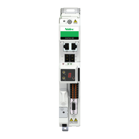
Page 9: Drive Features
Drive features Figure 1-2 Feature diagram (Frame 2 shown) Table 1-2 Key to features of the drive Number Description Braking terminals AC supply terminals DC bus terminal cover Communication port connections External 24 V supply terminals Status and communication LEDS Reset Display connection SD card slot... -
Page 10: Mechanical Installation
6 mm (0.24 in) 40 mm (1.58 in) * Cut outs only required for rear venting, refer to the Digitax HD M75X Series Installation and Technical Guide for further information. Table 2-1 Dimensions by frame size (refer to Figure 2-1) M2 (Ø)*... -
Page 11: Electrical Installation
Connections are located at the top and bottom of the drive, for further information refer to the Digitax HD M75X Series Installation and Technical Guide. For EMC (Electromagnetic compatibility) requirements refer to the Digitax HD M75X Series Installation and Technical Guide. -
Page 12: Terminal Size And Torque Settings
Terminal size and torque settings Table 3-3 Drive terminal data Recommended Terminal description Max cable size Min cable size Tool torque 0.5 mm AC power terminal connector 0.7 N m (6.2 lb in) 6 mm (8 AWG) (20 AWG) 0.5 mm Motor power terminal connector 0.5 N m (4.4 lb in) 4 mm... -
Page 13: Getting Started
Getting started Display and Keypad operation The drive can be operated with a KI-Compact Display or KI-Remote Keypad RTC. Only the KI-Remote Keypad RTC can be used to view and edit parameters. Connection to the drive can be established via a KI-Compact 485 Adaptor (all M75X variants) or via a drive communication port (M751 only) and a suitable Cat 5E patch cord. -
Page 14: Quick Start Commissioning / Start-Up
Quick start commissioning / start-up User drive Action Detail mode* Ensure: • The drive enable signal is not given (terminal 2 & 6) Before power-up • Run signal is not given • Run signal is not given • Motor and feedback device are connected Verify that the required user drive mode is displayed on the KI-Remote Keypad RTC as the drive powers up. -
Page 15: Quick Start Commissioning / Start-Up Using Connect
Drive is now ready to run. * The Digitax HD M75X series are factory configured in RFC-S mode. ** For simplicity only an incremental quadrature encoder with commutation outputs are considered here. For more information on setting up one of the other supported feedback devices, refer to the relevant Digitax HD M75X Control User Guide. - Page 16 4.3.1 Power-up the drive Start Connect, and on the ‘Project Management’ screen select ‘Scan serial RTU network’ (M751 only when connected to the drive communication port or all variants when connecting via the KI-Compact 485 Adaptor), ‘Scan Ethernet network’ (M750 only or M753 when using Ethernet over EtherCAT protocol) or ‘Scan all connected drives’.
-
Page 17: Current Limits
• Select ‘Default parameters‘ from the Dashboard and in the ‘Default Parameters’ dialog, select ‘Apply’. If the required control mode is not highlighted in the ‘Drive Settings’ dialog then: • Select the required mode and supply frequency. • Select ‘Apply’. 3. -
Page 18: Digitax Hd M75X Ul Listing Information
The Digitax HD M75X Series Installation and Technical Guide gives details of all safety-relevant adjustments intended for the user. The identification or function of each control or indicating device and fuse is clearly marked in the diagrams in the Digitax HD M75X Series Installation and Technical Guide. -
Page 19: Electrical
Short circuit current rating All drives: 5 kA when protected by Listed fuses as specified in the Digitax HD M75X Series Installation and Technical Guide. 100 kA when protected by recognised supplemental fuses as specified in the Digitax HD M75X Series Installation and Technical Guide. -
Page 20: Environmental
• Reduce the need for a secondary enclosure fan. Refer to the ‘Mechanical Installation’ (Chapter 3) of the Digitax HD M75X Series Installation and Technical Guide. For compact multi axis installations, the rear venting kit allows drives to be vertically mounted one above the other, where this is the case, a minimum clearance of 100 mm (3.94 in) should be... - Page 21 5.3.4 Pollution degree Drives are designed for operation in a pollution degree 2 environment or better (dry, non-conductive pollution only). 5.3.5 Plenum rating The drives are not suitable for installation in a compartment (duct) handing conditioned air. Digitax HD M75X Quick Start Guide Issue Number: 2...
- Page 22 Digital I/O 10 V Analog I/O common Analog input 1+ Frequency common reference 1 Analog input 1- common common common 24 V user Digital input 4 Run forward External 24 V supply Digital input 5 terminals Run reverse Digital output 1 Digital output 2 Safe Torque STO1...
Need help?
Do you have a question about the Digitax HD M75X Series and is the answer not in the manual?
Questions and answers
What is the meaning of message E020