Cambium Networks PTP 820S Installation Manual
System release 10.0
Hide thumbs
Also See for PTP 820S:
- Technical description (208 pages) ,
- User manual (672 pages) ,
- Quick start manual (23 pages)
Table of Contents
Advertisement
Quick Links
Advertisement
Table of Contents

Related Manuals for Cambium Networks PTP 820S


Summary of Contents for Cambium Networks PTP 820S
- Page 1 INSTALLATION GUIDE PTP 820S and PTP 820S Assured System Release 10.0...
- Page 2 Accuracy While reasonable efforts have been made to assure the accuracy of this document, Cambium Networks assumes no liability resulting from any inaccuracies or omissions in this document, or from use of the information obtained herein. Cambium reserves the right to make changes to any products described...
-
Page 3: Table Of Contents
Transportation and Storage ......................2-2 Unpacking ............................2-2 Inspection ............................2-2 Chapter 3: Product Hardware Description ..................3-1 PTP 820S Hardware Overview ......................3-2 PTP 820S Interfaces ........................3-3 PoE Injector ............................3-4 PoE Injector Interfaces ........................ 3-5 System Components ......................... 3-6 Adaptors and Installation Kits ...................... - Page 4 Preparing the Ethernet Cable and Plug-in Field ..............4-27 Preparing the Ethernet Cable Already Assembled ..............4-30 Connection of Ethernet Cable to PTP 820S ................4-31 Management Connection for 1+1 HSB Configurations ..............4-33 Preparing a Protection Signaling Cable .................. 4-33 Connecting the Protection Splitters and Protection Signaling Cable ........
- Page 5 Chapter 6: Generic Installation Procedures and Notes ..............6-1 Torque Requirements ........................6-2 Pole Mount Installation ........................6-3 PTP 820S DC Pole Mount Procedure ..................6-3 Chapter 7: PTP 820S Detailed Configurations Description ............7-1 1+0 Direct Mount Installation ......................7-2 List of Items ..........................
-
Page 6: List Of Figures
Contents List of Figures Figure 1 PTP 820S Rear View (Left) and Front View (Right) ..............3-2 Figure 2 Cable Gland Construction ......................3-2 Figure 3 PTP 820S Interfaces ........................3-3 Figure 4 PoE Injector ..........................3-4 Figure 5 PoE Injector Ports ........................3-5 Figure 6 System components ........................ -
Page 7: List Of Tables
Table 25 Required items for 2+0 Dual polarization direct mount configuration ....... 7-8 Table 26 Required items for 1+1HSB/2+0 Single Polarization Direct Mount configuration ... 7-14 Table 27 Required items for 1+1HSB/2+0 Single Polarization Remote Mount configuration ..7-17 Table 28 PTP 820S Mediation Device Losses ..................7-21 phn-3972 004v000 Page v... -
Page 8: About This User Guide
About This User Guide This guide describes the PTP 820S installation procedures and provides additional information concerning system parts and frequency bands This guide contains the following chapters: • Chapter 1: Product description • Chapter 2: Pre-Installation Instructions • Chapter 3: Product Hardware Description •... -
Page 9: Purpose
Problems and warranty Purpose Cambium Networks Point-To-Point (PTP) documents are intended to instruct and assist personnel in the operation, installation and maintenance of the Cambium PTP equipment and ancillary devices. It is recommended that all personnel engaged in such activities be properly trained. -
Page 10: Problems And Warranty
Cambium’s standard hardware warranty is for one (1) year from date of shipment from Cambium Networks or a Cambium distributor. Cambium Networks warrants that hardware will conform to the relevant published specifications and will be free from material defects in material and workmanship under normal use and service. -
Page 11: Security Advice
Security advice Security advice Cambium Networks systems and equipment provide security parameters that can be configured by the operator based on their particular operating environment. Cambium recommends setting and using these parameters following industry recognized security practices. Security aspects to be considered are protecting the confidentiality, integrity, and availability of information and assets. -
Page 12: Warnings, Cautions, And Notes
Warnings, cautions, and notes Warnings, cautions, and notes The following describes how warnings and cautions are used in this document and in all documents of the Cambium Networks document set. Warnings Warnings precede instructions that contain potentially hazardous situations. Warnings are used to alert the reader to possible hazards that could cause loss of life or physical injury. -
Page 13: Caring For The Environment
Caring for the environment The following information describes national or regional requirements for the disposal of Cambium Networks supplied equipment and for the approved disposal of surplus packaging. In EU countries The following information is provided to enable regulatory compliance with the European Union (EU) directives identified and any amendments made to these directives when using Cambium equipment in EU countries. -
Page 14: Chapter 1: Product Description
Chapter 1: Product description Cambium’s PTP 820S represents a new generation of radio technology, capable of high bit rates and longer reach, and suitable for diverse deployment scenarios. PTP 820S supports cutting edge capacity-boosting techniques, such as QPSK to 2048 QAM and Header De-Duplication, to offer a high capacity solution for every network topology and every site configuration. -
Page 15: Important Notes
• PTP 820S is intended for installation in a restricted access location. • PTP 820S must be installed and permanently connected to protective earth by qualified service personnel in accordance with applicable national electrical codes. phn-3972 004v000 Page 1-2... -
Page 16: Safety Precautions & Declared Material
Use of controls, adjustments, or performing procedures other than those specified herein, may result in hazardous radiation exposure. Caution When working with a PTP 820S, note the following risk of electric shock and energy hazard: Disconnecting one power supply disconnects only one power supply module. To isolate the unit completely, disconnect all power supplies. -
Page 17: Précautions Générales Relatives À L'équipement
Caution L’usage de PTP 820S s’accompagne du risque suivant d'électrocution et de danger électrique : le débranchement d'une alimentation électrique ne déconnecte qu'un module d'alimentation électrique. Pour isoler complètement l'unité, il faut débrancher toutes les alimentations électriques. - Page 18 Chapter 1: Product description Safety Precautions & Declared Material Caution Beachten Sie beim Arbeiten mit PTP 820S das folgende Stromschlag- und Gefahrenrisiko: Durch Abtrennen einer Stromquelle wird nur ein Caution Stromversorgungsmodul abgetrennt. Um die Einheit vollständig zu isolieren, trennen Sie alle Stromversorgungen ab.
-
Page 19: Chapter 2: Pre-Installation Instructions
Chapter 2: Pre-Installation Instructions This chapter describes the Pre-Installation instructions for PTP 820S. This chapter includes: • Packing • Transportation and Storage • Unpacking • Inspection phn-3972 004v000 Page 2-1... -
Page 20: Packing
Check the packing lists and ensure that correct parts numbers quantities of goods have arrived. Inspect for any damage on the cases and equipment. To report any damage or discrepancy to a Cambium Networks representative, use e-mail or fax. phn-3972 004v000... -
Page 21: Chapter 3: Product Hardware Description
Chapter 3: Product Hardware Description This chapter describes the PTP 820S components, interfaces and mediation devices. This chapter includes: • PTP 820S Hardware Overview • PoE Injector • System Components • Adaptors and Installation Kits • Antenna Connection • Power Specifications •... -
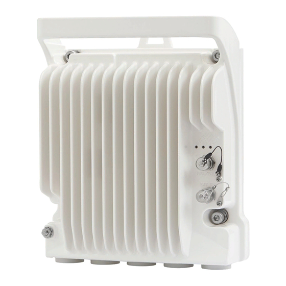
Page 22: Ptp 820S Hardware Overview
Chapter 3: Product Hardware Description PTP 820S Hardware Overview PTP 820S Hardware Overview PTP 820S features an all-outdoor architecture consisting of a single unit directly mounted on the antenna. Figure 1 PTP 820S Rear View (Left) and Front View (Right) -
Page 23: Ptp 820S Interfaces
Chapter 3: Product Hardware Description PTP 820S Hardware Overview PTP 820S Interfaces Figure 3 PTP 820S Interfaces • Data Port 1 for GbE traffic: Electric: 10/100/1000Base-T. Supports PoE. Optical: 1000Base-X (optional) • Data Port 2 for GbE traffic: Electric10/100/1000Base-T Optical: 1000Base-X (optional) •... -
Page 24: Poe Injector
Chapter 3: Product Hardware Description PoE Injector PoE Injector The PoE injector is an outdoor unit which can be mounted on a wall, pole or indoor rack. Each PoE Injector kit includes the following items: • PoE injector • 2 caps Figure 4 PoE Injector The following table listst the Cambium-approved PoE Injector: Table 1 PoE Injector part number... -
Page 25: Poe Injector Interfaces
Chapter 3: Product Hardware Description PoE Injector PoE Injector Interfaces • Power-Over-Ethernet (PoE) Port • GbE Data Port supporting 10/100/1000Base-T • DC Power Port 1 ±(18-60)V or ±(40-60)V • DC Power Port 2 ±(18-60)V • Grounding screw Figure 5 PoE Injector Ports phn-3972 004v000 Page 3-5... -
Page 26: System Components
Chapter 3: Product Hardware Description System Components System Components The following figures show the main components used in the PTP 820S installation procedures. Note In general, the PTP 820S utilizes the exact same mediation devices as the RFU-C, unless stated otherwise. -
Page 27: Adaptors And Installation Kits
Chapter 3: Product Hardware Description Adaptors and Installation Kits Adaptors and Installation Kits Table 2 Adaptors and installation kits for 6 to 18 GHz Description 6GHz 7-8GHz 10-11GHz 13GHz 15GHz 18GHz RFU-C Coupler KIT N060082L145A N070082L301A N110082L090A N130082L058A N150082L080A N180082L046A RFU-C Symmetrical N060082L149A N070082L305A... -
Page 28: Table 4 Remote Mount - 6 To 15 Ghz
Chapter 3: Product Hardware Description Adaptors and Installation Kits Table 4 Remote Mount – 6 to 15 GHz Remote Mount 6 GHz 7 GHz - 8GHz 10 GHz - 11GHz 13 GHz 15 GHz RFU-C Remote N000082L121A N000082L121A N000082L121A N000082L121A N000082L121A Mount KIT PTP 820C DC... -
Page 29: Table 6 Antenna Circ. Adapters For Omt For 6 To 18 Ghz
Chapter 3: Product Hardware Description Adaptors and Installation Kits Table 6 Antenna Circ. Adapters for OMT for 6 to 18 GHz Antenna Circ. 6GHz 7-8GHz 10-11GHz 13GHz 15GHz 18GHz Adapters for OMT N060082L147A N070082L303A N110082L092A N130082L060A N150082L082A N180082L048A CommScope N060082L154A N070082L310A N110082L103A N130082L068A... -
Page 30: Antenna Connection
Chapter 3: Product Hardware Description Antenna Connection Antenna Connection PTP 820S can be mounted directly for all frequencies (6-38 GHz) using the following antenna types (for integrated antennas, specific antennas part numbers are required): • CommScope: VHLP series • Radiowaves: HP series •... -
Page 31: Power Specifications
Chapter 3: Product Hardware Description Power Specifications Power Specifications Electrical Requirements • -48V DC Nominal • Maximum current rating 1.5 A • Maximum Cable length 300 meter • Maximum cable size for PoE cable is 24 AWG, with maximum current up to 2A from the power source. -
Page 32: Environmental Specifications
Chapter 3: Product Hardware Description Environmental Specifications Environmental Specifications Operating: ETSI EN 300 019-1-4 Class 4.1 Temperature range for continuous operating temperature with high reliability: -33°C (-27°F) to +55°C (131°F) Temperature range for exceptional temperatures; tested successfully, with limited margins: -45°C (-49°F) to +60°C (140°F) Humidity: 5%RH to 100%RH IEC529 IP66... -
Page 33: Chapter 4: Cable Installation And Grounding
Chapter 4: Cable Installation and Grounding This chapter describes the PTP 820S cable installation and grounding procedure. This chapter includes: • Minimum and Maximum Cable Diameter • Cable Grounding • Surge Protection • Securing the Cables • Available Cable Options •... -
Page 34: Minimum And Maximum Cable Diameter
To fit the gland, the outer cable diameter should be between 6-10 mm. This applies to all glands on both the PTP 820S unit and the PoE Injector. To fit the grounding clamp, the outer diameter of CAT5E Ethernet Cables must be between 6- 7.1mm. -
Page 35: Cable Grounding
Chapter 4: Cable Installation and Grounding Cable Grounding Cable Grounding Cables must be grounded as follows: • For fiber cables (see Connecting an Optical Fiber Cable and SFP on page 4-20), no grounding is required. • For DC power cables (see connecting a DC power cable on page 4-24), no grounding is required. - Page 36 Chapter 4: Cable Installation and Grounding Cable Grounding Place the cable in the middle of the grounding bracket. Close the grounding bracket around the cable. Tighten the two screws to secure the grounding bracket around the cable. phn-3972 004v000 Page 4-4...
-
Page 37: Grounding The Ptp 820S Unit
Metric offset wrench key wrench #3 • Metric wrench 10mm Procedure On the front of each PTP 820S unit, loosen the nut, plain washer and serrated washer from the GND stud, using the metric offset hexagon key and the wrench. phn-3972 004v000 Page 4-5... - Page 38 Chapter 4: Cable Installation and Grounding Cable Grounding Place the cable lug (supplied with the grounding kit) on the screw. Secure the cable lug. The second side of the GND cable should be connected to the main ground bar or terminal ground bar of the site.
-
Page 39: Power Source
The power supply must have grounding points on the AC and DC sides. Caution The user power supply GND must be connected to the positive pole in the PTP 820S power supply. Any other connection may cause damage to the system. -
Page 40: Surge Protection
Surge Protection Surge Protection PTP 820S includes built-in surge protection for its Ethernet and power interfaces. PTP 820S’s surge protection implementation complies with surge immunity standard IEC 61000-4-5, level 4, provided the Ethernet cables were prepared according to the instructions in... -
Page 41: Securing The Cables
Chapter 4: Cable Installation and Grounding Securing the Cables Securing the Cables All cables must be secured at every meter on-site using a suitable Outdoor Cable Tie. Take special care to apply the proper amount of force in order to avoid damage to the cable. This is especially important for optical (SFP) cables. -
Page 42: Available Cable Options
Chapter 4: Cable Installation and Grounding Available Cable Options Available Cable Options Fiber Optic Cables Table 11 Fiber Optic cables part numbers Marketing P/N Description N000082L139A PTP 820 Optical cable, SM, 30m N000082L140A PTP 820 Optical cable, SM, 50m N000082L141A PTP 820 Optical cable, SM, 80m N000082L142A PTP 820 Optical cable, SM, 100m... -
Page 43: Outdoor Ethernet Cable Specifications
Chapter 4: Cable Installation and Grounding Available Cable Options Figure 8 Cable design • [1]Conductor • [2]Insulation • [3]Screen: Alu/Pet foil. Alu outside • [4]Tinned copper braid • [5]Jacket Table 14 Ethernet cable Color Code Pair Wire A Wire B WHITE-blue BLUE WHITE-orange... -
Page 44: Outdoor Dc Cable Specifications
Chapter 4: Cable Installation and Grounding Available Cable Options Voltage rating Shielding Braid + Foil Pinout Ethernet Cable Mechanical/ Environmental Requirements Jacket UV resistant Outer diameter 7.1mm (in order to be compatible with the grounding clamp, CAT5E gnd kit) Operating and Storage -40°C - 85°C temperature range Flammability rating... - Page 45 Chapter 4: Cable Installation and Grounding Available Cable Options Jacket PVC, double, UV resistant Outer diameter 7-10 mm Operating & Storage -40°C - 85°C temperature range Flammability rating According to UL-1581 VW1, IEC 60332-1 RoHS According to Directive/2002/95/EC phn-3972 004v000 Page 4-13...
-
Page 46: Special Instructions For Use Of Glands
Special Instructions for use of Glands Special Instructions for use of Glands Note Each PTP 820S unit is supplied with two glands. If additional glands are required, they must be ordered separately, in kits of five glands each. Table 17 Glands kit... -
Page 47: General Installation Procedure
Chapter 4: Cable Installation and Grounding Special Instructions for use of Glands Figure 10 Removing glands General Installation Procedure This procedure applies to all cable types, and explains how to install the cables using long glands. The gland is supplied assembled. Before inserting a cable, you must disassemble the gland cap and gland rubber from the gland body Slide the gland cap into the cable. - Page 48 Chapter 4: Cable Installation and Grounding Special Instructions for use of Glands Slide the gland rubber into the cable. Slide the cable into the body of the gland. If a gland cap is being used (see Step 5), make sure to leave enough space for the gland cap to fit into the gland without disturbing the cable.
- Page 49 Chapter 4: Cable Installation and Grounding Special Instructions for use of Glands If an M28 gland cap is used to close the gland when raising the gland and cable to the radio unit, remove the gland cap from the gland at this point by unscrewing the cap. Connect the cable to the port.
- Page 50 Chapter 4: Cable Installation and Grounding Special Instructions for use of Glands Insert the main part of the gland into the thread in the radio body and tighten until there is full contact and the gasket is fully contained between the gland and the radio and cannot be seen.
- Page 51 Chapter 4: Cable Installation and Grounding Special Instructions for use of Glands phn-3972 004v000 Page 4-19...
-
Page 52: Connecting An Optical Fiber Cable And Sfp
Chapter 4: Cable Installation and Grounding Connecting an Optical Fiber Cable and SFP Connecting an Optical Fiber Cable and SFP To connect an optical fiber cable and the SFP transceiver: Use a pre-assembled cable. Split the connector into two separate LC Connectors (one for each fiber). Remove the gland cap and rubber from the gland body. - Page 53 Remove the tie wrap securing the cable to the gland. Note A new tie wrap must be used to secure the cable to the gland at the end of the procedure, as described in Step 13. Connect the connector into the PTP 820S LC connector. phn-3972 004v000 Page 4-21...
- Page 54 Chapter 4: Cable Installation and Grounding Connecting an Optical Fiber Cable and SFP Tighten the gland to the radio unit until there is full contact between the gland and the radio unit. Tighten the gland cap. Note Before tightening the gland, ensure it is aligned with the taped hole in the unit. Tightening the gland at an angle can ruin the thread on the gland and prevent proper sealing of the interface Tighten the gland gently and make sure there is no resistance.
- Page 55 Chapter 4: Cable Installation and Grounding Connecting an Optical Fiber Cable and SFP phn-3972 004v000 Page 4-23...
-
Page 56: Connecting A Dc Power Cable
Chapter 4: Cable Installation and Grounding Connecting a DC Power Cable Connecting a DC Power Cable To connect a DC power cable: Strip off 45 mm from the cable jacket. Expose 10 mm at the edge of each of the two wires. Insert the power cable into the gland. - Page 57 Chapter 4: Cable Installation and Grounding Connecting a DC Power Cable Tighten the two top screws. Plug the power cable with connector into the PTP 820S power connector. Tighten the two front screws. Screw the gland into the radio unit...
- Page 58 Chapter 4: Cable Installation and Grounding Connecting a DC Power Cable Caution Before tightening the gland, make sure the gland is even with the cover. Tighten the gland gently and make sure there is no resistance. If there is resistance, stop immediately and verify that the gland is not being inserted at an angle.
-
Page 59: Connecting The Ethernet Cable
Chapter 4: Cable Installation and Grounding Connecting the Ethernet Cable Connecting the Ethernet Cable If you need to assemble the Ethernet cable, follow the instructions in section Preparing the Ethernet Cable and Plug-in Field, then proceed to section Connection of Ethernet Cable to PTP 820S. - Page 60 Chapter 4: Cable Installation and Grounding Connecting the Ethernet Cable CAT5E_gnd_kit High speed GND KIT for CAT5e SF/UTP 5.9- 7.1mm outdoor cable GBE_connector_kit RJ45 CAT5E CONNECTORS AND BOOTS KIT (package of 10 connectors) To prepare the Ethernet cable and plug-in field: Prepare the gland and insert the cable, as described in General Installation Procedure on page 4-15...
- Page 61 Chapter 4: Cable Installation and Grounding Connecting the Ethernet Cable Wrap the twisted braid firmly around the cable jacket and let the crimping tail of the RJ45 plug envelop it. Caution To ensure proper grounding, it is essential that the twisted braid be firmly connected to the RJ45 plug.
-
Page 62: Preparing The Ethernet Cable Already Assembled
Chapter 4: Cable Installation and Grounding Connecting the Ethernet Cable Note It is recommended that the newly prepared cable be tested with a Cable Analyzer such as the FLUKE DTX-1800 (or the equivalent), to make sure the cable complies with ANSI/TIA/EIA-568-B-2. -
Page 63: Connection Of Ethernet Cable To Ptp 820S
Connection of Ethernet Cable to PTP 820S To connect the Ethernet cable to the PTP 820S: Remove the relevant cap from the PTP 820S radio. You can use the side of the gland to unscrew the cap. Connect the CAT5E cable to the PTP 820S. - Page 64 Chapter 4: Cable Installation and Grounding Connecting the Ethernet Cable Tighten the gland cap. Secure the cable to the gland using a tie wrap. phn-3972 004v000 Page 4-32...
-
Page 65: Management Connection For 1+1 Hsb Configurations
Configurations In HSB protection configurations, two Y-splitter cables and a special signaling cable must be used to connect the management ports (MGT/PROT) of the two PTP 820S units and provide management access to each unit. The Protection signaling cables are available pre-assembled from Cambium in various lengths, but users can also prepare them in the field. -
Page 66: Connecting The Protection Splitters And Protection Signaling Cable
Connecting the Protection Splitters and Protection Signaling Cable Each splitter has three ports: • System plug (“Sys”) – The system plug should be connected to the PTP 820S’s management port. • Management port (“Mng”) – A standard CAT5E cable should be connected to the splitter’s management port in order to utilize out-of-band (external) management. -
Page 67: Chapter 5: Poe Injector Installation And Connection
Chapter 5: PoE Injector Installation and Connection This chapter describes the PTP 820S PoE Injector installation and connection procedure. This chapter includes: • PoE Injector Cable Connection • PoE Injector Grounding • PoE Injector Wall Mount Installation • PoE Injector 19” Rack Installation •... -
Page 68: Poe Injector Cable Connection
• The total length of the cable between the PTP 820S port and the Switch/Router the device is connected to must not exceed 100m/328ft. This length includes the connection between the PTP 820S and the PoE Injector (X1 + X2 ≤ 100m/328ft in the figure below). -
Page 69: Poe Injector Grounding
Chapter 5: PoE Injector Installation and Connection PoE Injector Grounding PoE Injector Grounding To ground the PoE Injector: • On the right side of each PoE Injector, loosen the screw, plain washer and serrated washer. • Place the cable lug (supplied with the PoE injector kit) between the plain and serrated washer. •... -
Page 70: Poe Injector Wall Mount Installation
Chapter 5: PoE Injector Installation and Connection PoE Injector Wall Mount Installation PoE Injector Wall Mount Installation List of Items Table 19 Required items for Wall Mount PoE Injector Item Description Quantity Remarks PoE Injector Required Tools • Metric offset wrench key wrench set •... - Page 71 Chapter 5: PoE Injector Installation and Connection PoE Injector Wall Mount Installation phn-3972 004v000 Page 5-5...
-
Page 72: Poe Injector 19" Rack Installation
Chapter 5: PoE Injector Installation and Connection PoE Injector 19” Rack Installation PoE Injector 19” Rack Installation List of Items Table 20 Required item for 19” Rack Installation PoE Injector Item Description Quantity Remarks PoE Injector PoE Injector 19” Rack Mount KIT Required Tools •... - Page 73 Chapter 5: PoE Injector Installation and Connection PoE Injector 19” Rack Installation Mount the 19” rack adaptor to a 19” rack using four M6 screws and cage nuts. phn-3972 004v000 Page 5-7...
-
Page 74: Poe Injector Etsi Rack Installation
Chapter 5: PoE Injector Installation and Connection PoE Injector ETSI Rack Installation PoE Injector ETSI Rack Installation List of Items Table 21 Required items PoE Injector ETSI Rack Item Description Quantity Remarks PoE Injector PoE Injector ETSI Rack Mount KIT Required Tools •... - Page 75 Chapter 5: PoE Injector Installation and Connection PoE Injector ETSI Rack Installation Mount the PoE Injector on the adaptor through the wall mounting holes using M6 screws and washers. Mount the 19” rack adaptor with the ETSI ears on the ETSI rack using four M6 screws and cage nuts.
-
Page 76: Chapter 6: Generic Installation Procedures And Notes
Chapter 6: Generic Installation Procedures and Notes This chapter describes the generic nstallation procedure and notes for PTP 820S. This chapter includes: • Torque Requirements • Pole Mount Installation phn-3972 004v000 Page 6-1... -
Page 77: Torque Requirements
Chapter 6: Generic Installation Procedures and Notes Torque Requirements Torque Requirements When tightening the captive screws, use 20 Nm torque for radio-antenna, radio-mediation device, and mediation device-antenna connections. In order to avoid misalignment, screws should be tightened progressively. When fastening a waveguide to the radio or mediation device, use the following torque, according to frequency and screw type: •... -
Page 78: Pole Mount Installation
Metric offset wrench key wrench set Procedure Mount and tighten the PTP 820S DC pole mount to a pole with a diameter of 114 mm using the four washers and screws supplied with the PTP 820S DC pole mount kit. -
Page 79: Chapter 7: Ptp 820S Detailed Configurations Description
Chapter 7: PTP 820S Detailed Configurations Description This chapter describes the PTP 820S detailed configuration description. This chapter includes: • 1+0 Direct Mount Installation • 2+0 Dual Polarization Direct Mount • 2+0 Dual Polarization Remote Mount • 1+1HSB/2+0 Single Polarization Direct Mount •... -
Page 80: 1+0 Direct Mount Installation
• Metric offset hexagon key wrench #6 • Phillips #2 screwdriver Procedure To install the PTP 820S in a direct mount 1+0 configuration: Caution Do not remove the transparent pressure window located on the antenna interface. phn-3972 004v000 Page 7-2... -
Page 81: Figure 15 Horizontal / Vertical Pole
Chapter 7: PTP 820S Detailed Configurations Description 1+0 Direct Mount Installation Note If necessary, change the antenna polarization by rotating the unit in accordance with the relevant antenna installation guide. Figure 15 Horizontal / Vertical Pole Figure 16 Twist orientation... - Page 82 PTP 820S. The horizontal iris (MA-1840-X, PTP 820S Twist 6Ghz Horizontal) is included in the PTP 820S. Mount the PTP 820S on the antenna using the four M8 captive screws and washers that are supplied and tighten the screws.
-
Page 83: 2+0 Dual Polarization Direct Mount
Chapter 7: PTP 820S Detailed Configurations Description 2+0 Dual Polarization Direct Mount 2+0 Dual Polarization Direct Mount Figure 17 2+0 Dual Polarization Direct Mount Note This procedure can also be used for 1+0DP HW ready for 2+0 DP configuration. List of Items... - Page 84 Chapter 7: PTP 820S Detailed Configurations Description 2+0 Dual Polarization Direct Mount Connect the RFU-C OMT Kit to the antenna and secure it with four screws. Verify the existence of the O-ring. Mount the two O-Rings supplied with the RFU-C OMT kit on the OMT body. Make sure the mounting direction is correct, as shown in the section view.
- Page 85 Chapter 7: PTP 820S Detailed Configurations Description 2+0 Dual Polarization Direct Mount Mount both RFUs, using the four M8 captive screws and washers supplied, through the radio and OMT holder, and tighten the screws. Make sure the polarization mounting direction is correct.
-
Page 86: 2+0 Dual Polarization Remote Mount
Chapter 7: PTP 820S Detailed Configurations Description 2+0 Dual Polarization Remote Mount 2+0 Dual Polarization Remote Mount Note This procedure can also be used for 1+0DP HW ready for 2+0 DP configuration. Figure 18 2+0 Dual Polarization Remote Mount List of Items... -
Page 87: Common Installation Procedures
Chapter 7: PTP 820S Detailed Configurations Description 2+0 Dual Polarization Remote Mount Common Installation Procedures Prior to the installation, follow the antenna manufacturer’s instructions to use the circular adaptor. (Remove the existing rectangular transition, swap the O-ring, and install the circular transition instead.) - Page 88 Chapter 7: PTP 820S Detailed Configurations Description 2+0 Dual Polarization Remote Mount This procedure is applicable for all remote mount configurations that involve an OMT. For 6Ghz (UDR70): Mount the O-Ring supplied with the OMT kit. Mount OMT Adaptor #1 on the OMT, and tighten using four M4 screws and washers (supplied with the OMT adaptor kit).
- Page 89 Chapter 7: PTP 820S Detailed Configurations Description 2+0 Dual Polarization Remote Mount Mount the OMT adaptor, with its installed sealing gasket, on the OMT, and tighten using the four M4 screws and washers supplied with the OMT Adaptor kit. Mount the flexible waveguide without its gasket (only for the OMT side).
- Page 90 Chapter 7: PTP 820S Detailed Configurations Description 2+0 Dual Polarization Remote Mount Mount the PT 820S Radio to RFU-C Pole Mount Bracket using the four captive screws and washers supplied, assembled, in the PTP 820S. Connect the Flexible Waveguide and sealing O-Ring supplied with the Flexible Waveguide Imperial kit.
- Page 91 Chapter 7: PTP 820S Detailed Configurations Description 2+0 Dual Polarization Remote Mount Frequencies 6-13 GHz require remote mount adaptors. phn-3972 004v000 Page 7-13...
-
Page 92: 1Hsb/2+0 Single Polarization Direct Mount
Phillips #2 screwdriver • Metric offset hexagon key wrench #2.5 and #3 Procedure In 1+1 direct mount installation, the PTP 820S is attached to a coupler. To install a PTP 820S in a direct mount 1+1 configuration: phn-3972 004v000 Page 7-14... - Page 93 Chapter 7: PTP 820S Detailed Configurations Description 1+1HSB/2+0 Single Polarization Direct Mount Note For 15 and 18 GHz frequencies, two O-Rings are supplied in the Twist kit and must be mounted in the twist grooves. For 6 GHz frequency, a gasket is used instead of an O-Ring. The gasket must be mounted between the twist and the RFU-C Coupler kit.
- Page 94 Mount the two O-Rings supplied with the RFU-C Coupler kit, as shown in the following figure. Mount the PTP 820S to the body of the coupler using the four M8 captive screws and washers that are supplied and tighten the screws.
-
Page 95: 1Hsb/2+0 Single Polarization Remote Mount
Chapter 7: PTP 820S Detailed Configurations Description 1+1HSB/2+0 Single Polarization Remote Mount 1+1HSB/2+0 Single Polarization Remote Mount Note This procedure can also be used for 1+0SP HW ready for 2+0SP configuration. Figure 20 1+1HSB/2+0 Single Polarization Remote Mount ACCP List of Items... -
Page 96: Procedure
Procedure In 1+1 remote mount installation, the PTP 820S radios are attached to a coupler, while the coupler is connected to the antenna via flexible WG. To install the PTP 820S in a remote mount 1+1 configuration: Mount the RFU-C coupler to the RFU-C pole mount bracket using the four M8 screws and washers supplied with the RFU-C Coupler kit, and tighten the screws. - Page 97 Chapter 7: PTP 820S Detailed Configurations Description 1+1HSB/2+0 Single Polarization Remote Mount Mount the PTP 820S radio to the body of the coupler using the four M8 captive screws and washers that are supplied, assembled, in the PTP 820S, and tighten the screws.
- Page 98 Chapter 7: PTP 820S Detailed Configurations Description 1+1HSB/2+0 Single Polarization Remote Mount phn-3972 004v000 Page 7-20...
-
Page 99: Mediation Device Losses
Mount antenna Note The antenna interface is always the PTP 820S interface. If other antennas are to be used, an adaptor with a 0.1 dB loss must be considered. The numbers above represent the typical loss per component. phn-3972 004v000... -
Page 100: Chapter 8: Acceptance And Commissioning Procedures
Chapter 8: Acceptance and Commissioning Procedures Mediation Device Losses Chapter 8: Acceptance and Commissioning Procedures This chapter provides Cambium's recommended Acceptance and Commissioning Procedure for PTP 820. Acceptance and commissioning should be performed after initial setup is complete. The purpose of this procedure is to verify correct installation and operation of the installed link and the interoperability with customer end equipment. -
Page 101: Site Acceptance Procedure
Chapter 8: Acceptance and Commissioning Procedures Site Acceptance Procedure Site Acceptance Procedure The purpose of the following procedures is to verify that all installation requirements were noted and checked. Following this procedure will ensure proper, long-lasting, and safe operation of the product. - Page 102 Chapter 8: Acceptance and Commissioning Procedures Site Acceptance Procedure Antenna sealing O-Ring is properly fitted and not damaged Antenna/Launch unit polarization is as per link requirements SITE ACCEPTANCE CHECKLIST (continued) 4. OUTDOOR UNIT Type of ODU mount: (Direct or Remote mount) ODU is securely mounted to the antenna or pole ODU is grounded as per installation instructions ODU‘s polarization is as per link requirements...
- Page 103 Chapter 8: Acceptance and Commissioning Procedures Site Acceptance Procedure SITE ACCEPTANCE CHECKLIST (continued) 7. FLEXIBLE WAVEGUIDE Overall flexible WG length: Flexible WG type: Flexible WG is connected securely to ODU and Antenna Flexible WG connector is weather-proofed (sealed) at the ODU At the ODU, the flexible WG has a service/drip loop to prevent moisture from entering the connector Flexible WG is secured using suitable restraints to...
- Page 104 Chapter 8: Acceptance and Commissioning Procedures Site Acceptance Procedure SITE ACCEPTANCE CHECKLIST (continued) 10. REMARKS/NOTES 11. GENERAL INFORMATION Name: Title: Site accepted by: Company: Signature: Date: Name: Title: Site approved by: Company: Signature: Date: phn-3972 004v000 Page 8-26...
-
Page 105: Site Acceptance Checklist Notes
Chapter 8: Acceptance and Commissioning Procedures Site Acceptance Checklist Notes Site Acceptance Checklist Notes The following notes provide important additional information about the Site Acceptance Checklist. 1. Antenna Mounting Mounting pole is of sufficient height to clear local obstructions, such as parapets, window cleaning gantries, and lift housings. - Page 106 Chapter 8: Acceptance and Commissioning Procedures Site Acceptance Checklist Notes • Antenna labels - for link identity and bearing • ODU labels - for link identity, frequency, and polarization • Cat5/Fiber cable labels - for link identity, close to the ODU, switch, and either end of any joint •...
-
Page 107: Radio Link Commissioning Procedure
Chapter 8: Acceptance and Commissioning Procedures Radio Link Commissioning Procedure Radio Link Commissioning Procedure Scope This section describes the recommended commissioning tests for PTP 820 radio link in a 1+0 configuration. The purpose of the commissioning tests is to verify correct and proper operation of the product. Commissioning Test The following tests should be performed on each installed link. - Page 108 Chapter 8: Acceptance and Commissioning Procedures Radio Link Commissioning Procedure Management Verification • Launch the HTTP management and verify that you can manage the link and that you are able to perform changes to the link configuration (frequency channel, Tx power, system name, time &...
-
Page 109: Ptp 820 Commissioning Log
Maintaining the Commissioning Log is important for tracking your installations, and to provide essential data for Cambium Networks. Upon completing the Commissioning Log, send the log to Cambium Networks’ support center at https://support.cambiumnetworks.com.. PTP 820 LINK COMMISSIONING LOG 1. - Page 110 Chapter 8: Acceptance and Commissioning Procedures PTP 820 Commissioning Log Mounting losses: Site 1 Site 2 4. LINK PARAMETERS Link distance: Rain zone: Expected RSL (dBm): Expected Diversity RSL (dBm): RSL Main (dBm): RSL Diversity (dBm): Deviation from exp? RSL ≤4 dB? Site 1 Site 2 5.
Need help?
Do you have a question about the PTP 820S and is the answer not in the manual?
Questions and answers