
Related Manuals for Fluke T6-1000


Summary of Contents for Fluke T6-1000
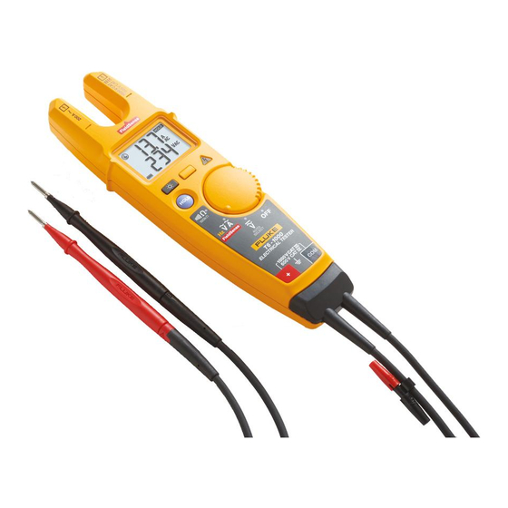
- Page 1 T6-1000/T6-600 Electrical Tester Service Information February 2018 ©2018 Fluke Corporation. All rights reserved. All product names are trademarks of their respective companies. Specifications are subject to change without notice.
- Page 2 LIMITED WARRANTY AND LIMITATION OF LIABILITY Each Fluke product is warranted to be free from defects in material and workmanship under normal use and service. The warranty period is two years and begins on the date of shipment. Parts, product repairs, and services are warranted for 90 days.
-
Page 3: Table Of Contents
How to Contact Fluke ........ - Page 4 T6-1000/T6-600 Service Information...
-
Page 5: How To Contact Fluke
The information provided in this manual is for the use of qualified personnel only. This service information is for the T6-600 and T6-1000 Electrical Testers (the Product). For complete operating instructions, see the Quick Reference Guide provided with your product. - Page 6 T6-1000/T6-600 Service Information • Examine the case before you use the Product. Look for cracks or missing plastic. Carefully look at the insulation around the terminals. • Examine the battery door decal for damage to this insulator. Look for any cracks, holes, or evidence of delamination.
- Page 7 Symbol Description WARNING. RISK OF DANGER. WARNING. HAZARDOUS VOLTAGE. Risk of electric shock. Consult user documentation. FieldSense Measurement: Fluke voltage/current sensing technique. Double Insulated Application around and removal from uninsulated hazardous live conductors is permitted. Earth Both direct and alternating current ...
-
Page 8: Specifications
General ..............IEC 61010-1: Pollution Degree 2 Measurement ............IEC 61010-2-032, IEC 61010-2-033 T6-600 ..............CAT III 600 V T6-1000 ............CAT IV 600 V / CAT III 1000 V Electromagnetic Compatibility (EMC) International ............IEC 61326-1: Portable Electromagnetic Environment CISPR 11: Group 1, Class A Group 1: Equipment has intentionally generated and/or uses conductively-coupled radio frequency energy that is necessary for the internal function of the equipment itself. -
Page 9: Required Equipment
9100-200 10/50-Turn Coil (Fluke PN 1583963) Performance Tests Fluke recommends a 1-year cycle for the Performance Tests. If the Product fails any test, return the Product to a Fluke Service Center or Authorized Service Partner. See How to Contact Fluke for more information. -
Page 10: Voltage Function
T6-1000/T6-600 Service Information Voltage Function Perform these tests as follows: Set the calibrator NORMAL output to the voltage listed in Table 5, Step 1. Table 5. AC Voltage Tests T6-600 T6-1000 Calibrator Display Limits Calibrator Display Limits Step Output (AC Annunciator ON) -
Page 11: Fieldsense Current Function
Set the Product to the FieldSense measurement mode. If needed, use the SHIFT (yellow) button on the Product to switch to AC Current mode and Frequency mode (T6-1000 only). Connect the 10/50-turn coil to the calibrator AUX HI and AUX LO jacks. - Page 12 Verify that the Product reading is within the display limits. Apply the test values for the remaining steps of Table 7. Verify the readings are within the display limits. Table 7. FieldSense Low Current Tests T6-600/T6-1000 T6-1000 only Calibrator Output Step (AUX HI)
-
Page 13: Fieldsense Voltage Function
FieldSense Voltage Function The tests in this section require the use of a PRV240FS Proving Unit (Fluke P/N 4910310) and a Fluke 8846A Multimeter. Set the 8846A to the AC Voltage measurement mode (ACV button) and range manually to the 1000 V range. -
Page 14: Low Battery Indicator
T6-1000/T6-600 Service Information Low Battery Indicator To verify the correct operation of the low battery indicator: Remove the Tester batteries. Set the dc power supply to 3.0 V. Apply this voltage to the Tester battery terminals and observe the correct polarity. -
Page 15: Maintenance
If the Product is used appropriately it does not require special maintenance or repair. See www.fluke.com for locations and contact information of Fluke Service Centers worldwide. How to Clean W Caution For safe operation and maintenance, clean the case with a damp cloth and detergent. Do not use abrasives or solvents. -
Page 16: Replacement Parts
T6-1000/T6-600 Service Information Replacement Parts Replacement parts and accessories are listed in Table 10. To order parts and accessories, see How to Contact Fluke. Table 10. Replacement Parts Fluke Part Ref. Description or Model Number Battery Door 4944370 ...
Need help?
Do you have a question about the T6-1000 and is the answer not in the manual?
Questions and answers