Fluke T5-600 Instruction Sheet
Hide thumbs
Also See for T5-600:
- User manual ,
- Service information (10 pages) ,
- Instruction sheet (4 pages)
Table of Contents
Advertisement
Quick Links
W Read First: Safety Information
Use the tester only as specified in this Instruction Sheet,
otherwise the protection provided by the tester may be
impaired.
•
Do not use the tester if it is damaged or operating
abnormally. Protection may be impaired.
•
Before each use:
Make sure the battery door is closed and latched.
Inspect the tester and test leads. Look for cracks,
missing plastic, exposed metal, or damaged
insulation. Replace damaged test leads before using
the tester.
Verify the tester's operation by measuring a known
voltage.
Perform the Battery Test to avoid false readings due
to a low battery.
•
Replace the batteries as soon as the low battery
indicator (M) appears.
•
Do not use the tester around explosive gas, vapor or
dust.
•
Do not apply more than the rated voltage, as marked on
the tester, between terminals or between any terminal
and earth ground.
•
When servicing the tester, use only specified
•
Use caution when working above 30 V ac rms, 42 V ac
peak, or 60 V dc.
•
When using the probes, keep your fingers behind the
finger guards on the probes.
•
Connect the common test lead before you connect the
live test lead. Disconnect the live test lead first.
B
AC (alternating current)
F
DC (direct current)
W
Safety Information
(Refer to the manual)
Voltage Indicator
While the tester is on, the LED glows when more than 30 V ac or
60 V dc is present across the leads.
The LED can also glow at lower voltages. Be aware that such
voltages pose a shock hazard.
PN 688374 (English) July 1997, Rev. 1, 9/98
© 1997-1998 Fluke Corporation, All rights reserved. Printed in U.S.A.
All product names are trademarks of their respective companies.
T5-600 / T5-1000
W
Warning
Symbols
M
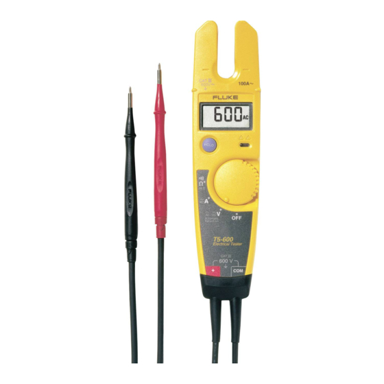
Electrical Tester
Instruction Sheet
J
Earth ground
T
Double insulated
Battery
®
Advertisement
Table of Contents

Related Manuals for Fluke T5-600


Summary of Contents for Fluke T5-600
- Page 1 The LED can also glow at lower voltages. Be aware that such voltages pose a shock hazard. PN 688374 (English) July 1997, Rev. 1, 9/98 © 1997-1998 Fluke Corporation, All rights reserved. Printed in U.S.A. All product names are trademarks of their respective companies.
- Page 2 The tester defaults to ac voltage when turned on. DC Voltage AC Voltage T5-600 maximum: 600 V 45 Hz to 66 Hz T5-600 maximum: 600 V rms T5-1000 maximum: 1000 V T5-1000 maximum: 1000 V rms CAT III CAT III...
- Page 3 Measuring AC Current (A) • Range: 0 A to 100.0 A; 45 Hz to 66 Hz 0.5"(12.9 mm) • Remove probes from test maximum points. • Place conductor anywhere within the sensor zone (shaded area shown below). ex1.eps Sensor Zone ex5.eps Display Hold To hold the reading on the display, press and release HOLD.
-
Page 4: Specifications
Specifications Calibration: One-year calibration cycle. Maximum Voltage Between any Terminal and Earth Ground: T5-600: 600 V rms, Overvoltage Category III; T5-1000: 1000 V rms, Overvoltage Category III Temperature: Operating: -10 °C to +50 °C (14 °F to 122 °F); Storage: -30 °C to +60 °C (-22 °F to +140 °F) Altitude: Operating: 2000 m (6562 ft);... - Page 5 MIL-PRF-28800F for a Class 2 instrument (5 Hz to 55 Hz, 3 g maximum). Surge Protection: T5-600 6 kV per IEC 1010-1, 1990-09; T5-1000 8 kV per IEC 1010-1, 1990-09 Enclosure Rating: IP 52 per IEC 529, no vacuum applied RF Field Specification: 0.5 % full scale + (specified accuracy)
- Page 6 Limited Warranty & Limitation Of Liability This Fluke product will be free from defects in material and workmanship for two years from the date of purchase. This warranty does not cover fuses, disposable batteries, or damage from accident, neglect, misuse or abnormal conditions of operation or handling.
Need help?
Do you have a question about the T5-600 and is the answer not in the manual?
Questions and answers