Table of Contents
Advertisement
Quick Links
User Guide for the Evaluation Kit ATA8520-EK1-E and the
ATA8520-EK2-E and ATA8520-EK3-E Extension Boards
Features
●
User guide for the evaluation kit ATA8520-EK1-E and extension boards
ATA8520-EK2-E and ATA8520-EK3-E
●
This kit demonstrates a Flash application with the
●
ATA8520-EK1-E evaluation kit:
®
with the Atmel
SIGFOX
®
ATmega328P AVR
battery-powered kit for standalone operation
●
ATA8520-EK2-E and
Includes Atmel SIGFOX ATA8520D V1.3 transceiver device with an AT30TS75A
temperature monitoring device. An additional MCU application development kit,
i.e. Xplained mini or Arduino UNO is required.
Description
This user guide describes an evaluation kit and the extension boards for a SIGFOX
application. This application uses an Atmel ATmega328P AVR microcontroller to
read out an AT30TS75A temperature sensor using the built-in TWI connection and controls
the RF telegram transmission using the SIGFOX ATA8520D V1.3 transceiver device. This
application requires a SIGFOX base station infrastructure to capture the RF telegram and
supply payload data at the SIGFOX back end of the SIGFOX Cloud. For more information
on operating the SIGFOX network and SIGFOX Cloud, see
information.
The evaluation and development kit tool packs are available for download from the Atmel
website: http://www.atmel.com/devices/ATA8520.aspx. These tool packs include
●
The ATAN0054 quick start guide for the kit and the Atmel ATAN0104 user guide
●
The schematic, layout and Gerber data for the ATAB0101A PCB
●
The source code for the Atmel ATmega328P as an Atmel Studio 6 project
The Atmel ATA8520D SIGFOX transceiver is a SIGFOX-certified device which includes the
complete SIGFOX protocol stack to operate in the SIGFOX network within the 868MHz
ISM band. The device is controlled from any host MCU using the SPI commands as
described in the datasheet [1]. Included in the tool pack is a ATA8520D library as C source
code for the SPI commands.
APPLICATION NOTE
™
ATA8520D V1.3 transceiver device and an Atmel
microcontroller with AT30TS75A temperature sensor as a
ATA8520-EK3-E
extension boards:
ATAN0104
http://www.sigfox.com
9373E-AUTO-11/15
Advertisement
Table of Contents

Related Manuals for Atmel ATA8520-EK3-E


Summary of Contents for Atmel ATA8520-EK3-E
-
Page 1: Application Note
SIGFOX network and SIGFOX Cloud, see http://www.sigfox.com information. The evaluation and development kit tool packs are available for download from the Atmel website: http://www.atmel.com/devices/ATA8520.aspx. These tool packs include ● The ATAN0054 quick start guide for the kit and the Atmel ATAN0104 user guide ●... - Page 2 References ® Atmel ATA8520D datasheet and user guide Atmel AT30TS75A datasheet http://www.sigfox.com http://backend.sigfox.com http://www.atmel.com/devices/ATA8520.aspx Atmel ATAN0054 – ATA8520-EK1-E/EK2-E/EK3-E quick start guide ATA8520-EK123-E_Tool_pack_V1.0.zip ATAN0104 [APPLICATION NOTE] 9373E–AUTO–11/15...
-
Page 3: Getting Started With The Ata8520-Ek1-E Kit
40-50s. The Atmel ATA8520D device includes the SIGFOX ID and PAC registration code (see label attached to PCB) to register the kit with the user's account for the SIGFOX back end. The user has to open a SIGFOX cloud account to access the back end. -
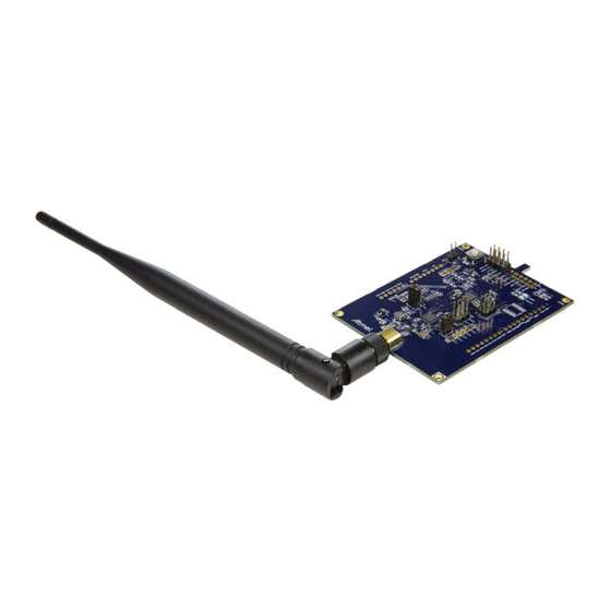
Page 4: Getting Started With The Ata8520-Ek2-E And -Ek3-E Extension Boards
2-1): to be used with an additional Xplained mini (Figure 2-2) or Arduino UNO kit ● An ATA8520-EK3-E Xplained Pro (Figure 2-3): to be used with an additional Xplained Pro kit (Figure 2-4) Figure 2-1. ATA8520-EK2-E Xplained Mini Extension Board with Attached External Antenna Figure 2-2. - Page 5 The 868MHz monopole antenna is connected to the SMA connector of the PCB and the board is powered from the attached evaluation kit using 3V/5V for the ATA8520-EK2-E Xplained Mini and 3V for the ATA8520-EK3-E Xplained Pro. The following Flash applications are available as part of tool pack distribution: ●...
- Page 6 The Atmel debugger included in the development kits can be used for application development. Application development and use of the debugger is only possible if Atmel Studio 6 is installed in the front end. Atmel Studio 6 can be downloaded from http://www.atmel.com...
-
Page 7: Tool Pack For The Kits
868MHz ISM band. The ATA8520D device can also receive payload data with 8 Bytes from the SIGFOX cloud when transmitting an uplink/downlink request. The Atmel ATA8520D device is certified by SIGFOX to participate in their network. A second certification step for the module or system including antenna is also required with a classification of the module or system RF performance, i.e. -
Page 8: Atab0101A Pcb Description
Includes the connectors X3, X4, X5 and X6 for connecting the PCB on top of an Xplained mini or an Arduino UNO board Operating mode with an additional Xplained Pro kit for the ATA8520-EK3-E extension board using a SAMD21: ●... - Page 9 ● Supply voltage divider connected to pin ADC0 to measure the supply voltage against the internal 1.1V reference ● Includes the footprint for the following TWI sensor devices: BMP180 air pressure sensor HTU20D / SHT20 humidity sensor ● Includes the connector X2 to for connecting the PCB to an Xplained Pro board Figure 5-1.
- Page 10 Flash application during a telegram transmission. This allows the calculation of a mean current consumption depending on the wake-up intervals. The shown current profile is a typical profile and depends on the Flash application of the Atmel ATmega328P device and the attached sensors.
- Page 11 PCB versions are used. The placement of the connectors at the PCB is shown in Figure 5-1 on page Table 5-2. ATAB0101A Connectors ATA8520-EK1-E ATA8520-EK3-E ATA8520-EK2-E Connector Standalone Version Xplained Pro Extension Xplained Mini Extension X1 ext. power...
- Page 12 5.2.2 Connector X2 Connector X2 is used for connecting to an Xplained Pro MCU kit. In this connection mode the PCB is supplied with 3V of power from the Xplained Pro MCU board. Table 5-4. Connector X2 Function Function ID_data PC0 (PB00) SW1 (PB01) PB1/RF_NRES (PB06)
- Page 13 Connector X6 Function PD2/RF_EVNT PD3/SNS_PWR PD5/LED1 PD6/SW1 PD7/AES_NSS 5.2.4 Connector X7 ® Connector X7 is not typically mounted. These Atmel ATA8520D pins can also be used as supplementary I/O pins. Table 5-9. Connector X7 Function RPC1/RF_NPRON1 RPC2/RF_TRPA RPC3/RF_TMDO RPC4/RF_TMDI RPC5/RF_TRPB...
- Page 14 5.2.5 Connector X8 Connector X8 is not typically mounted and is used for the TWI bus connection with the switched power supply. This connector can be used to attach additional sensors and devices with the TWI connection. The power consumption is limited to ~50mA.
- Page 15 ATmega328P and to the connectors X2/pin8 and X6/pin6 and can be controlled by the MCU application. The button SW1 is connected to port PD6 on Atmel ATmega328P and to the connectors X2/pin4 and X6/pin7 and can be read by the MCU application.
-
Page 16: Application Description
External 32.768kHz crystal for the ATA8520-EK1-E kit or the ● Internal system clock for the ATA8520-EK2-E and ATA8520-EK3-E kits. Timer2 is configured to wake up the MCU every hour or every 15 minutes. Pressing button SW1 also causes the MCU to wake up. - Page 17 ® Atmel Studio 6 is required for software development and can be downloaded from the Atmel website [5]. The tool pack [7] with software and documentation is also required. When unpacking the tool pack, the folder structure as described in Section 3.
-
Page 18: Revision History
Section 1 “Getting Started with the ATA8520-EK1-E Kit” on page 3 updated 9373E-AUTO-11/15 ATAK55002-V1 to ATA8520-EK1-E renamed ATAK55002-V2 to ATA8520-EK2-E renamed ATAK55002-V3 to ATA8520-EK3-E renamed 9373D-AUTO-10/15 Section 4 “ATA8520D SIGFOX Certified Transceiver” on page 7updated Section 5 “ATAB0101A PCB Description” on pages 8 to 14 updated Section 6 “Application Description”... - Page 19 DISCLAIMER: The information in this document is provided in connection with Atmel products. No license, express or implied, by estoppel or otherwise, to any intellectual property right is granted by this document or in connection with the sale of Atmel products. EXCEPT AS SET FORTH IN THE ATMEL TERMS AND CONDITIONS OF SALES LOCATED ON THE ATMEL WEBSITE, ATMEL ASSUMES NO LIABILITY WHATSOEVER AND DISCLAIMS ANY EXPRESS, IMPLIED OR STATUTORY WARRANTY RELATING TO ITS PRODUCTS INCLUDING, BUT NOT LIMITED TO, THE IMPLIED WARRANTY OF MERCHANTABILITY, FITNESS FOR A PARTICULAR PURPOSE, OR NON-INFRINGEMENT.
Need help?
Do you have a question about the ATA8520-EK3-E and is the answer not in the manual?
Questions and answers