Table of Contents
Advertisement
Quick Links
Advertisement
Table of Contents
Troubleshooting

Related Manuals for aoyue INT 2702A+


Summary of Contents for aoyue INT 2702A+
- Page 1 ® AOYUE 2702A+ Lead-Free Repairing System INSTRUCTION MANUAL Thank you for purchasing Aoyue Int2702A+ Repairing System. It is important to read the manual before using the equipment. Please keep manual in accessible place for future reference.
-
Page 2: Table Of Contents
This manual is designed to familiarize and instruct the operator with the proper usage and maintenance of the equipment. The “Care and Safety Precautions” section explains the hazards of using any type of soldering or reworking device. Please read carefully and observe the guidelines in order to maximize usage and minimize the risk of injury or accidents . -
Page 3: Product Description
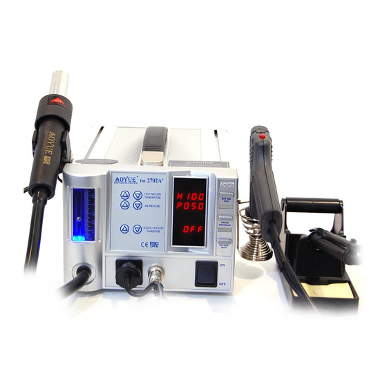
PRODUCT DESCRIPTION The Aoyue I 2702A+ Lead-Free Repairing System is a reworking equipment that combines the functionality of Hot Air Gun, Soldering Iron, Smoke Absorber, and Desoldering Gun in one package. It has several safety features such as the auto-cooling process of the Hot Air Gun. -
Page 4: Package Inclusion
PACCKAGE INCLUSIONS 1 unit Int2702A+ Main Station with Hot Air Gun and holder. 1 pc. 1124 Air Nozzle 1 pc. 1130 Air Nozzle (Single ø4.4mm) 1 pc. 1197 Air Nozzle (Single ø9 mm) 1 pc. 1313 Air Nozzle 1 pc. 30202X Plastic Mesh Cover 1 pc. -
Page 5: Functions And Features
FUNCTION and FEATURES Microprocessor-controlled ESD safe equipment. ● 4-in-1 repairing system combining Hot Air Gun, Soldering Iron, ● Smoke Absorber and Desoldering Gun in one sophisticated package. Digital control and display of hot air temperature, soldering iron ● temperature, desoldering gun temperature and air pressure with touch type panel controls for precision and ease of use. -
Page 6: Safety Precautions
SAFETY PRECAUTIONS CAUTION: Improper usage can cause serious injury to personnel and/or damage to equipment. For your own safety, please observe the ff. precautions. Check each component after opening the package to make sure ● everything is in good condition. If there are any suspected damage, do not use the item and report the issue to your vendor. -
Page 7: Assembly And Preparation
ASSEMBL Y and PREPARATIONS A. Main Station As soon as the equipment has been removed from the package, REMOVE THE SCREW located at the center of the bottom of the main unit. This screw holds the pump in place during transportation. Failure to remove the screw before using the WARNING: equipment can cause damage to the system. -
Page 8: Control Panel Guide
CONTROL PANEL GUIDE LEGEND: 1 — Airflow Gauge 2 — Hot Air Gun Temperature Adjustment Buttons 3 — Hot Air Gun Airflow Adjustment Buttons 4 — Soldering Iron / Desoldering Gun Temp Control Buttons 5 — Hot Air Gun Output Terminal 6 —... -
Page 9: Operating Guidelines
OPERATING GUIDELINES IMPORTANT REMINDERS: 1. Make sure the equipment is placed on a flat stable surface and all the heat-generating components placed on their re- spective holders or stands. 2. Ensure all function switches are OFF prior to reworking. 3. Ensure all terminal connections are properly secured. IMPORTANT : Please refer to the CONTROL PANEL GUIDE page for buttons and display panel directory. - Page 10 OPERATING GUIDELINES 4. Adjust the air flow level using the AIR PRESSURE ADJUSTMENT BUTTONS (“3” from the control panel). 5. Adjust the hot air gun air temperature using the HOT AIR GUN TEMPERATURE ADJUSTMENT BUTTONS (“2” from the control panel). The prefix of the display for Hot Air Gun Temperature will change from “H”...
- Page 11 OPERATING GUIDELINES NOTES: 1. Hot Air Gun Temperature is adjustable between 100° and 480°C with an increment of 2° on each step. 2. Hot Air Gun Airflow Rate is adjustable between 10 and 100 with an increment of 2 on each step. C.
- Page 12 OPERATING GUIDELINES 3. Connect the vacuum tube to the Smoke Absorber Terminal or Vacuum Cap (“6” from the control panel). If smoke absorber function is to be used. 4. Activate the “SOLDER IRON” Activation switch (“9” from control panel). This will automatically start to increase the temperature of the desoldering gun to 350°C (default).
-
Page 13: Auto-Sleep Functions
AUTO SLEEP FUNCTIONS The soldering iron and desoldering gun operating temperature is ● configurable between 200°C and 480°C Because of the difference in the heating element and size of the ● soldering iron tip and desoldering gun, the soldering iron will heat up faster than the desoldering gun. - Page 14 AUTO SLEEP FUNCTIONS 1. While the hot air gun is on stand-by mode (“0FF” is displayed on the panels “13” and “12”), hold both UP and DOWN buttons of the HOT AIR GUN TEMPERATURE adjustment buttons. 2. Wait until “t005” is displayed on the Hot Air Gun Temperature display panel, “13”.
-
Page 15: Digital Calibration
DIGITAL CALIBRATION Release the two buttons after the change in display. Use the same two buttons to adjust the countdown time. “t001” means solder iron will go to sleep in 1 minute. Timer is adjustable from 1 to 60minutes. Confirm the change by activating the SOLDERING IRON switch. To DEACTIVATE this feature, simply follow the above procedures. - Page 16 DIGITAL CALIBRATION Adjust the temperature compensation using the UP and DOWN buttons of the Soldering iron adjustment buttons. A zero “0” on the first digit signifies addition to the current temperature and a minus “-” on the first digit will subtract the displayed value from the current settings.
- Page 17 DIGITAL CALIBRATION NOTES: The calibrated data is saved into the memory an shall remain ● effective until it is recalibrated again or new data is entered. If the maximum of 70 degrees has already been added or ● subtracted pressing the air pressure down button would not exit from calibration mode.
-
Page 18: Care And Maintenance
CARE and MAINTENANCE Spare Parts Guide Part No. Description 10094 Hot air gun heating element 30106S Plastic handle of hot air gun S009 Hot air gun complete handle 20962 Hot air gun metal pipe B012 Soldering Iron complete handle C005 Desoldering gun heating element 3072D Plastic handle of desoldering gun... - Page 19 CARE and MAINTENANCE Inside the pipe, the quartz glass and heat insulation are installed. Loosen the cable and take out the heating element. Insert new heating element and reconnect the terminal. Be careful not to rub Heating Element wire. Reconnect the ground wire after replacing the element. Assemble the handle again.
-
Page 20: Care And Maintenance
CARE and MAINTENANCE Changing nozzle: Unscrew the securing lock and pull out the heater external housing to- ● gether with the securing lock, Nozzle can now be changed. Re-secure nozzle by tighten the securing lock on its receptacle. Changing Filter pad and Filter Spring: ●... -
Page 21: Basic Troubleshooting Guide
BASIC TROUBLESHOOTING GUIDE PROBLEM 1: THE UNIT HAS NO POWER Check if the unit is switched ON. Check the fuse. Replace with the same type if fuse is blown. Check the power cord and make sure there are no disconnections. Verify that the unit is properly connected to the power source. -
Page 22: Basic Troubleshooting Guide
BASIC TROUBLESHOOTING GUIDE PROBLEM 7: AIR PRESSURE LEVEL IS SIGNIFICANTLY LOW NO MATTER HOW HIGH THE AIRFLOW LEVEL IS CALIBRATED Case 1: Check the mains voltage (AC power source). If the voltage level falls significantly low, about 15-20% lower than the standard, there will also be a noticeable drop in the air pressure level. -
Page 23: Replacement Tips
Manufacturer: AOYUE INTERNATIONAL LIMITED Jishui Industrial Zone, Nantou, Zhongshan City, Guangdong Province, P.R.China http://www.aoyue.co... -
Page 24: Air Nozzles
22mm 22mm SERIES SERIES Replacement Air Nozzles MODEL# IC SIZE L(mm) W(mm) SGL SERIES MODEL# IC SIZE 1010 9×9mm L(mm) W(mm) A(mm) B(mm) 1131 4.4×10mm 10.3 1313 12×12mm 1616 15×15mm 1132 5.6×13mm 11.7 1919 18×18mm 1133 7.5×15mm 2828N 27×27mm 1134 7.5×18mm 3030N 29×29mm...
Need help?
Do you have a question about the INT 2702A+ and is the answer not in the manual?
Questions and answers