Advertisement
BASIC TROUBLESHOOTING GUIDE
PROBLEM 1: THE UNIT HAS NO POWER
1.
Check if the unit is switched ON.
2.
Check the fuse. Replace with the same type if fuse is blown.
3.
Check the power cord and ensure there are no disconnections.
4.
Verify that the unit is properly connected to the power source.
PROBLEM 2: PANEL DISPLAYS " " MESSAGES
DESCRIPTION: Display show " "
A — Temperature probe A not detected
b — Temperature probe b not detected
C — Temperature probe C not detected
F— Solder Iron not attached.
SOLUTION: Turn off power and back on. Check the connection of externals
sensors, Top heater tool and solder iron, connect plugs properly into its
receptacle. Check if the temperature probe tip is still intact.
PROBLEM 3: DISPLAY AND OTHER DEVICE OPERATION
ISSUES
SOLUTION: Turn off power and back on.
OTHER PROBLEMS NOT MENTIONED:
Contact the vendor.
AOYUE TONGYI ELECTRONIC EQUIPMENT FACTORY
Jishui Industrial Zone, Nantou, Zhongshan City, Guangdong Province, P.R.China
www.aoyue.com
Copyright © 2010 Aoyue Tongyi International Ltd.
16
aoyue
Game Console Reworking System
INSTRUCTION MANUAL
Thank you for purchasing Aoyue Int732 Game Console Reworking System.
It is important to read the manual before using the equipment.
Please keep manual in accessible place for future reference.
This manual is designed to familiarize the technician with
the proper operation and maintenance of the equipment.
The "Care and Safety Precautions" section explains the
hazards of using any type of soldering or reworking device.
Please read carefully and observe the guidelines in order to
maximize usage and minimize the risk of injury or accidents .
®
Int732
Advertisement
Table of Contents

Related Manuals for aoyue Int732


Summary of Contents for aoyue Int732
- Page 1 BASIC TROUBLESHOOTING GUIDE PROBLEM 1: THE UNIT HAS NO POWER 1. Check if the unit is switched ON. ® aoyue 2. Check the fuse. Replace with the same type if fuse is blown. Int732 3. Check the power cord and ensure there are no disconnections. 4. Verify that the unit is properly connected to the power source. Game Console Reworking System PROBLEM 2: PANEL DISPLAYS “ ” MESSAGES DESCRIPTION: Display show “ ” A — Temperature probe A not detected b — Temperature probe b not detected INSTRUCTION MANUAL C — Temperature probe C not detected F— Solder Iron not attached. SOLUTION: Turn off power and back on. Check the connection of externals ...
-
Page 2: Table Of Contents
OPERATING PROCEDURES To check the slope from segment Two : 150C 180C =30C ● Time to reach 150C is set to 110seconds. ● TABLE OF CONTENTS Therefore the slope is 60/110= 0.54 degrees per second increase. ● Note: a negative number would denote a declining slope. CARE & SAFETY PRECAUTIONS ………………..………….. 3 PRODUCT DESCRIPTION …………………………………… 4 FUNCTIONS & FEATURES …………………………………… 4 PACKAGE INCLUSION …………………………………….. 6 SPECIFICATIONS ……………………………….……………. 6 OPERATING PROCEDURES ……………………………... 715 BASIC TROUBLESHOOTING GUIDE …………………….. -
Page 3: Care & Safety Precautions
OPERATING PROCEDURES CARE and SAFETY PRECAUTIONS 7. To see the running time, or current segment the system is processing or the CAUTION: Improper usage can cause injury and physical damage. temperature of the external temperature probes. repeatedly press the For your own safety, please observe the following precautions. selection button to switch between different views. Follow the suffix guide to determine displayed temperature. Temperature may reach as high as 500°C when turned ON. ● 8. After the process is finish the display will show “End”, ... -
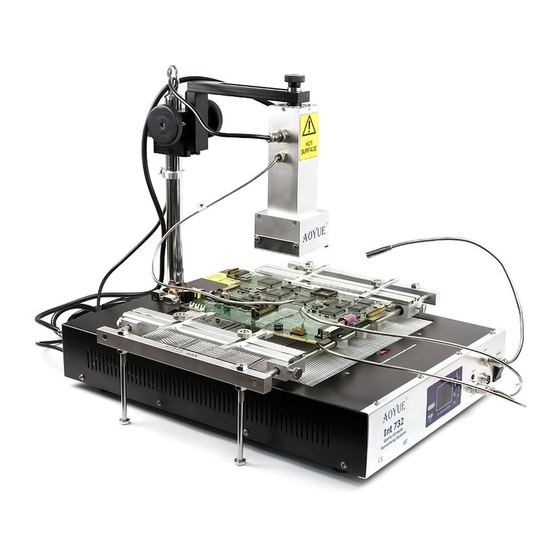
Page 4: Product Description
OPERATING PROCEDURES PRODUCT DESCRIPTION The Aoyue Int732 Game Console Repairing System is a reworking equipment Note: During segments 13 the top heater heats up to 75% of the set temperature that utilizes infrared (IR) heating technology, to provide top and bottom heating to at these segments. This is to allow a faster ramp up in preparation for reflow for ... - Page 5 OPERATING PROCEDURES FUNCTIONS and FEATURES ● MultiPoint Board Holder 6. To view the actual temperature read by the three external temperature — Innovative board holder: Nine securing screws with four side grips to sensor, repeatedly press the selection button until the top display shows the provide a secure fit for various board sizes and shapes. Effectively minimizes top ...
-
Page 6: Package Inclusion
PACKAGE INCLUSION OPERATING PROCEDURES This type of operation utilizes the external temperature probe A to regulate the top heater, while the external temperature probe b regulates the heat of the Nozzles bottom heater. Using this type of operation allows us to closely control the Soldering Iron Soldering Iron temperature at board level. While freeing up external temperature probe C for stand additional monitoring. ... - Page 7 OPERATING PROCEDURES CONTROL PANEL GUIDE 1.a 2 3 5 16 4. Press the increase or decrease button to adjust the bottom heater set temperature level. The set temperature is adjustable from 50 to 280 C in this type of operation. To temporarily turn off the bottom heater simultaneously 8 press both the “Increase” and “decrease” button (#3 & #4 from the control panel display see page 8) . The bottom display will show “OFF” indicating the Front Panel 1.b 1.c ...
- Page 8 OPERATING PROCEDURES OPERATING PROCEDURES A. INITIAL PROCEDURES 2. Press the increase or decrease button to adjust the set temperature level. The set temperature is adjustable from 200 to 480C. 1. Make sure all switches are deactivated. 3. For the solder iron actual temperature display. Follow TYPE “0” 2. Attach external sensor probes to the three pin socket (#6 on control panel (see page 10) OPERATION number 5 . guide) . ...
Need help?
Do you have a question about the Int732 and is the answer not in the manual?
Questions and answers