Table of Contents
Advertisement
Advertisement
Table of Contents

Related Manuals for aoyue INT2703A+


Summary of Contents for aoyue INT2703A+
- Page 1 ® AOYUE 2703A+ Advanced Lead-Free Repairing System INSTRUCTION MANUAL Thank you for purchasing Aoyue Int2703A+ Repairing System. It is important to read the manual before using the equipment. Please keep manual in accessible place for future reference.
-
Page 2: Table Of Contents
This manual is designed to familiarize and instruct the op- erator with the proper usage and maintenance of the equipment. The “Care and Safety Precautions” section explains the hazards of using any type of soldering or re- working device. Please read carefully and observe the guidelines in order to maximize usage and minimize the risk of injury or accidents . -
Page 3: Product Description
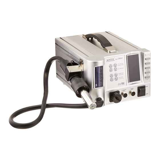
PRODUCT DESCRIPTION The Aoyue I 2703A+ Advanced Lead-Free Repairing System is a reworking equipment that combines the functionality of Hot Air Gun, Soldering Iron, Smoke Absorber, and Desoldering Gun in one package. The dual port system of the Int2703A+ allows simultaneous use of the desoldering gun and soldering iron. -
Page 4: Specifications
SPECIFICATION MAIN STATION Power Input : available in 110V / 220V Station Dimensions: 188(w) x 126(h) x 250(d) mm Weight: 5.6Kg SOLDERING IRON Power Consumption: Temperature Range: 200°C - 480°C Heating Element: Ceramic Heater Output Voltage: HOT AIR GUN Power Consumption: 500W Temperature Range: 100°C - 480°C... -
Page 5: Package Inclusion
PACCKAGE INCLUSIONS 1 unit Int2703A+ Main Station with Hot Air Gun and holder. 1 pc. 20094 Spare Heating Element (Hot Air Gun) 1 pc. 1130 Air Nozzle (Single ø4.4mm) 1 pc. 1197 Air Nozzle (Single ø9 mm) 1 pc. 3232W Multi-Chambered Air Nozzle (BGA 31 x 31 mm) 1 pc. -
Page 6: Functions And Features
FUNCTION and FEATURES Microprocessor-controlled ESD safe equipment. ● 4-in-1 repairing system combining Hot Air Gun, Soldering Iron, ● Smoke Absorber and Desoldering Gun in one sophisticated package. Advance technology air spreader nozzle ● Digital control and display of hot air temperature, soldering iron ●... -
Page 7: Safety Precautions
SAFETY PRECAUTIONS CAUTION: Improper usage can cause serious injury to personnel and/or damage to equipment. For your own safety, please observe the ff. precautions. Check each component after opening the package to make sure ● everything is in good condition. If there are any suspected damage, do not use the item and report the issue to your vendor. -
Page 8: Assembly And Preparation
ASSEMBL Y and PREPARATIONS A. Main Station As soon as the equipment has been removed from the package, REMOVE THE SCREW located at the center of the bottom of the main unit. This screw holds the pump in place during transportation. WARNING: Failure to remove the screw before using the equipment can cause damage to the system. -
Page 9: Control Panel Guide
CONTROL PANEL GUIDE ® AOYUE Int 2703A+ REPAIRING SYSTEM LEGEND: 1 — Airflow Gauge 2 — Hot Air Gun Temperature Adjustment Buttons 3 — Hot Air Gun Airflow Adjustment Buttons 4 — Soldering Iron Temperature Control Buttons 5 — Desoldering Gun Temperature Control Buttons 6 —... -
Page 10: Operating Guidelines
ON the device by activating the main power switch (“10” from the control panel). 3. The display panels, will temporarily show the product name “AOYUE Int 2702” and then display “OFF”. The system will remain at this state until the user activates a function. - Page 11 OPERATING GUIDELINES B. HOT AIR GUN 1. Follow initial procedures above, “A. INITIAL PROCEDURES”. 2. Activate “Hot Air Gun” switch (“19” from the control panel). 3. The system will immediately start to blow air at an airflow rate of 50 while rapidly and safely increasing the air temperature to 100°C (default system operating parameters).
- Page 12 OPERATING GUIDELINES 6. Reworking task can be started 1 minute after the desired hot air temperature and airflow level are reached, as also indicated from display panel “18” . 6. When reworking is complete, return the Hot Air Gun to its holder but DO NOT immediately turn off the main power switch.
- Page 13 OPERATING GUIDELINES 1. Ensure that the hot air gun function switch is deactivated. 2. The Hot Air Gun Automate Function Selector (“17” from the control panel) allows us to scroll thru the different stages of the profile. The stages use the symbols A, b, c, d and E, to indicate stages 1 to 5 respectively.
- Page 14 OPERATING GUIDELINES Upon the start of the automated reworking function the hot air gun would slowly heat up until it reaches the set temperature of segment A. After the set temperature is reached it would maintain the set tempera- ture for the duration as set in segment A. The displayed duration will start counting down until the timer reaches 0 after which it will proceed to the next segment, repeating the process until it finishes all 5 seg- ments.
- Page 15 OPERATING GUIDELINES 1. Start using the soldering iron as soon as desired temperature is reached. 2. When the task is finished, deactivate the SMOKE ABSORBER switch. 3. Deactivate the SOLDER IRON activation switch. 4. Allow sufficient time for the soldering iron to cool down before keeping in a safe storage.
- Page 16 OPERATING GUIDELINES 4. Upon pressing the pump trigger hold the trigger for 1 to 2 seconds longer, as larger lumps of solder may need a longer suction time to clear the barrel and go into the filter. 5. Clean the filter and dampen the sponge frequently during and after usage to allow better suction power.
- Page 17 OPERATING GUIDELINES F. Hot Air Gun Safety Feature The systems’ hot air gun has a safety feature to limit the temperature rise to no more than 3 degrees per second. The 3 degrees per second limit is an industry standard recommendation to minimize component damage due to a rapid increase of temperature.
-
Page 18: Auto-Sleep Functions
AUTO SLEEP FUNCTIONS G. Auto-Sleep Mode (Hot Air Gun) The device has a built-in auto-sleep mode feature such that if the Hot Air Gun sits on its handle and remained idle after a certain period the prefix of the display for Hot Air Gun air temperature will also change from “C”... - Page 19 AUTO SLEEP FUNCTIONS NOTES: The sleep mode timer is configurable between 1 and 60 minutes. ● A sleep mode timer value of “0” disables the sleep function. ● Sleep mode settings for Hot-Air gun is saved into the memory and ●...
- Page 20 AUTO SLEEP FUNCTIONS Changing SLEEP Timer (Desoldering Gun) By default, the system’s sleep duration is 0 indicating the sleep timer is disabled. To activate the sleep function follow the procedures. 1. Turn off the Soldering Iron Function switch (“14” from the control panel) .Ensure that the Desoldering Gun Function switch is in the off position(“12”...
-
Page 21: Digital Calibration
DIGITAL CALIBRATION J. Utilizing the Solder Iron Digital Temperature Calibration By default, the system is properly calibrated but for some cases when a little adjustment of the soldering iron temperature is required the following procedure can be done. 1. Turn on the soldering iron function switch. 2. - Page 22 DIGITAL CALIBRATION I. Utilizing the Desoldering Gun Digital Temperature Calibration 1. Turn on the Desoldering gun function switch. 2. Set to appropriate temperature you want to calibrate. Place the tip of the desoldering gun on an external temperature meter. 3. The readings on the external temperature sensor should be more or less equal to the displayed temperature.
- Page 23 DIGITAL CALIBRATION Solder Iron Digital Temperature Calibration Example The external temperature sensor displays 250 degrees. ● The set temperature and displayed actual temperature of the ● soldering iron is 300 degrees. 300 — 250 = 50. An additional adjustment of 50 degrees is ●...
-
Page 24: Care And Maintenance
CARE and MAINTENANCE Spare Parts Guide Part No. Description 10094 Hot air gun heating element 30106S Plastic handle of hot air gun S009 Hot air gun complete handle 20962 Hot air gun metal pipe B012 Soldering Iron complete handle C006A Desoldering gun heating element 3072D Plastic handle of desoldering gun... - Page 25 CARE and MAINTENANCE Inside the pipe, the quartz glass and heat insulation are installed. Loosen the cable and take out the heating element. Insert new heating element and reconnect the terminal. Be careful not to rub Heating Element wire. Reconnect the ground wire after replacing the element. Assemble the handle again.
-
Page 26: Care And Maintenance
CARE and MAINTENANCE Changing nozzle: ● Unscrew the securing lock and pull out the heater external housing together with the securing lock, Nozzle can now be changed. Re- secure nozzle by tighten the securing lock on its receptacle. Changing Filter pad and Filter Spring: Unlock the filter dock by toggling the filter dock locking mechanism. -
Page 27: Basic Troubleshooting Guide
BASIC TROUBLESHOOTING GUIDE PROBLEM 1: THE UNIT HAS NO POWER Check if the unit is switched ON. Check the fuse. Replace with the same type if fuse is blown. Check the power cord and make sure there are no disconnections. Verify that the unit is properly connected to the power source. - Page 28 BASIC TROUBLESHOOTING GUIDE PROBLEM 6: SOLDERING IRON TEMPERATURE DISPLAY PANEL SHOWS “PLUG” CHARACTERS Case 1: The system shows “PLUG” from the soldering iron temperature display panel . SOLUTION 1: Check if the soldering iron connection assembly is properly connected and secured to the receptacle on the control panel. SOLUTION 2: Make sure the soldering iron tip is properly inserted and secured inside the handle.
- Page 29 BASIC TROUBLESHOOTING GUIDE Case 3: The Suction Vacuum cap is connected to the Smoke Absorber Terminal or Vacuum cap instead of the Wire mesh cap. SOLUTION: Change the cap to the Wire mesh cap. This allows more air to pass through the system.
-
Page 30: Replacement Tips
REPLACEMENT SOLDERING TIPS... -
Page 31: Air Nozzles
22mm 22mm SERIES SERIES Replacement Air Nozzles MODEL# IC SIZE L(mm) W(mm) SGL SERIES MODEL# IC SIZE L(mm) W(mm) A(mm) B(mm) 1010 9×9mm 1131 4.4×10mm 10.3 1313 12×12mm 1616 15×15mm 1132 5.6×13mm 11.7 1919 18×18mm 1133 7.5×15mm 2828N 27×27mm 1134 7.5×18mm 3030N 29×29mm... - Page 32 They can take this product for environmental safe recycling. Manufacturer: AOYUE INTERNATIONAL LIMITED Jishui Industrial Zone, Nantou, Zhongshan City, Guangdong Province, P.R.China http://www.aoyue.co...
Need help?
Do you have a question about the INT2703A+ and is the answer not in the manual?
Questions and answers