Advertisement
Manufacturer:
AOYUE TONGYI ELECTRONIC EQUIPMENT FACTORY
Jishui Industrial Zone, Nantou, Zhongshan City,
Guangdong Province, P.R.China
http://www.aoyue.com
20
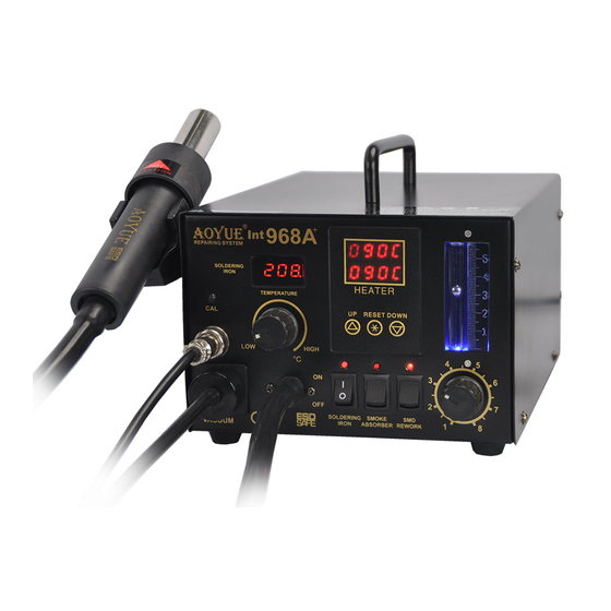
aoyue
DE LUXE REPAIRING SYSTEM
Thank you for purchasing Aoyue 968A+ Repairing System.
It is important to read the manual before using the unit.
Please keep manual in accessible place for future reference.
CAUTION
The temperature of the soldering iron, hot air gun and the nozzle ranges from 200
o
o
(400
~ 850
F) when the unit is switched ON. Injury to personnel or damage to items in the
workplace may result if not carefully used. Please read the contents on how to use the
equipment and observe the following in order to maximize usage:
●
After opening the package, check if each component is in good working condition. If
there are any suspected damages, do not use the item and report this to the dealer.
●
Turn OFF the power switch and unplug the unit from the main power source when
moving the equipment to another location.
●
Do not strike or subject the main unit to any physical shock, including the hot air gun,
soldering iron or any parts of the system. Use carefully to avoid damage in any parts.
●
Make sure the unit is grounded. Always connect power to a grounded receptacle.
®
+
968A
o
~ 480
o
C
Advertisement
Table of Contents

Related Manuals for aoyue 968A+


Summary of Contents for aoyue 968A+
- Page 1 ® + 968A DE LUXE REPAIRING SYSTEM Thank you for purchasing Aoyue 968A+ Repairing System. It is important to read the manual before using the unit. Please keep manual in accessible place for future reference. CAUTION o o The temperature of the soldering iron, hot air gun and the nozzle ranges from 200 ~ 480 C o o (400 ~ 850 F) when the unit is switched ON. Injury to personnel or damage to items in the workplace may result if not carefully used. Please read the contents on how to use the equipment and observe the following in order to maximize usage: ● After opening the package, check if each component is in good working condition. If ...
-
Page 2: Table Of Contents
BASIC TROUBLESHOOTING GUIDE PROBLEM 5: AIR PRESSURE LEVEL IS SIGNIFICANTLY LOW NO MATTER HOW HIGH THE AIRFLOW LEVEL IS CALIBRATED TABLE OF CONTENTS Case 1: Check the mains voltage (AC power source). If the voltage level falls significantly low, about 1520% lower than the standard, Package Inclusion ………………...……………………….. -
Page 3: Package Inclusion
PACKAGE INCLUSION BASIC TROUBLESHOOTING GUIDE PROBLEM 1: THE UNIT HAS NO POWER 1. Check if the unit is switched ON. G001 IC Popper 2. Check the fuse. Replace with the same type if fuse is blown. 3. Check the power cord and make sure there are no disconnections. 4. Verify that the unit is properly connected to the power source. Main Station o PROBLEM 2: TEMPERATURE DISPLAY IS ALWAYS ABOVE 500 C o Description: Constant display of above 500 C temperature from the Hot Air Gun and panel C3 then displays a blinking “OFF” on display panels C2 and C3 Hot Air Gun Holder ... -
Page 4: Functions And Features
FUNCTIONS and FEATURES MAINTENANCE SPARE PARTS LIST Microprocessorcontrolled electrostatic discharge (ESD) safe unit. ● Easytouse touch type panel controls with digital display. ● PART# NAME & SPECIFICATION Environmentfriendly repairing system that integrates hot air gun, ● 10094 Hot air gun heating element soldering iron, and smoke absorber in one package. 30105S Plastic handle of hot air gun Builtin smoke extractor that absorbs fumes created at the source. ● S005 Hot air gun complete handle Knob type soldering iron temperature control for simple yet efficient ● 20962 Hot air gun metal pipe working temperature selection. P003 Diaphragm pump Digital control and display of soldering iron temperature. ● C009 Soldering iron heating element Sleep mode for soldering iron. Soldering iron to go into sleep mode ● 30123S ... -
Page 5: Product Specifications
MAINTENANCE PRODUCT SPECIFICATION IMPORTANT: Unless otherwise directed, carry out these procedures Power Input : available in 110V & 220V with the power switched OFF and the power cord UNPLUGGED. Main Station Dimensions: 188(w) x 126(h) x 250(d) mm CARBON FILTER Weight: 5.25Kg K1 — filter drawer SOLDERING IRON K2 — active carbon filter pads (30181X) K3 —... -
Page 6: Care And Safety Precautions
2. Cleaning — Always clean the soldering tip before using. Remove any Do not use near paper, plastic, and flammable gases and materials. residual solder or flux that are still adhering to the tip. Use a clean and Do not touch heated parts. moist cleaning sponge to remove unwanted residues. For better results our Aoyue 98 and 128 tip cleaners are great alternatives for wet sponges that Do not touch metallic parts near the tip. cleans as good as wet sponges but does not lower tip temperature like wet Thermal Protector ● ... -
Page 7: Panel Controls
OPERATING GUIDELINES PANEL CONTROLS SOLDERING IRON MANUAL CALIBRATION C2 C3 1. Set soldering iron to desired working temperature. 2. Wait a few minutes for the temperature to stabilize before checking aoyue Int968A+ the temperature difference with an external calibrated probe. REPAIRING SYSTEM 3. Access the manual calibration hole by removing the rubber cover of the calibration hole. SOLDERING IRON 4. Use a small screw to slowly adjust the trimmer potentiometer thru the TEMPERATURE ... -
Page 8: Preparation
PREPARATION OPERATING GUIDELINES The soldering iron display A2 will turn to “##” or “0##” , ● A. Main Power indicating it is now on digital calibration mode. 1. Plug power cord into receptacle found at the back of the unit. Turn the soldering iron adjustment knob to set calibration to “ ● 00”. This resets the calibration to zero. Power let system save the calibration value into the memory. ● Switch 3. Set soldering iron to desired working temperature. 4. Wait a few minutes for the temperature to stabilize before checking ... - Page 9 OPERATING GUIDELINES OPERATING GUIDELINES To let system save the desired sleep timer value into the memory, SMD REWORKING ● 1. Ensure All function switches (B1,B2,B3) are in off position. simply let go of the adjustment knob and the system will 2. With the unit plugged to the main power source, turn on the automatically save the value into CPU memory. ...
- Page 10 OPERATING GUIDELINES OPERATING GUIDELINES 5. Set the desired air temperature using buttons A6 and A7. 5. After a few seconds the digital display A2 will switch to showing 6. You may start reworking as soon as the desired temperature is the actual temperature. You may start soldering when the desired reached. Refer to display panel C3 to verify. temperature has been reached. The small dot located at the end 7. When reworking is completed, turn off the “SMD Rework” of ...
Need help?
Do you have a question about the 968A+ and is the answer not in the manual?
Questions and answers