Table of Contents
Advertisement
Advertisement
Table of Contents

Subscribe to Our Youtube Channel
Related Manuals for ITRON 60W


Summary of Contents for ITRON 60W
- Page 1 60W Endpoint Installation Guide...
- Page 2 PUB-0771-001 Rev. A 01/06 Trademark Notice Itron is a registered trademark of Itron, Inc. All other product names and logos in this document are used for identification purposes only and may be trademarks or registered trademarks of their respective companies.
-
Page 3: Table Of Contents
Installing the 60W Endpoint ........7... - Page 4 60W Endpoint Installation Guide PUB-0771-001 Rev. A 01/06...
-
Page 5: List Of Procedures
List of Procedures Attaching a Cable Tie to the Connector ....... . . 6 Installing with the Rod Mount . - Page 6 60W Endpoint Installation Guide PUB-0771-001 Rev. A 01/06...
-
Page 7: Before You Begin
Before You Begin Overview The 60W is available with either a 5’ length of cable (not terminated) or with an inline connector (attached to approx. 7’’ of cable) and will interface with several encoded (absolute) registers. This document describes the installation of the 60W endpoint, including rod mount, wall mount, pipe mount and through-lid installations. - Page 8 60W Endpoint Installation Guide PUB-0771-001 Rev. A 01/06...
-
Page 9: Chapter 1 Getting Started
• The 60W will compare the hourly read with the Reverse Flow Detection previous read. If the current read is less than the previous read the 60W will report in the SCM that this occurred. Battery Life Powered by a non-replaceable long life dual lithium battery pack, the 60W end- point has an expected battery life of 20 years. -
Page 10: Included Materials
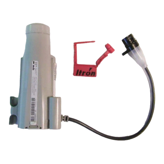
• 60W endpoint with inline connector (connector includes a protective cover) and security seal. • 60W endpoint with a 5’ cable (This configuration allows for connection directly to the register terminals.). • Connector cables in 5-foot and 25-foot lengths. Itron typically supplies these cables to the meter manufacturer for potting to the register. -
Page 11: Installation Process Overview
Installation Process Overview Installation Process Overview Mount Inline Connector Mount register Put unit in according to installation Manufacturers mode recommended procedure Connect inline connector Verify the 60W is operating properly Chapter 1 - Getting Started PUB-0771-001 Rev. A 01/06... -
Page 12: Compatible Registers
Compatible Registers Compatible Registers The following water meter registers are compatible with the 60W. • AMCO Scancoder • AMCO InVision • Badger ADE (To be released at a later date) • Hersey Translater (To be released at a later date) •... - Page 13 Compatible Registers Figure 4: Badger ADE with factory assembled inline connector and cable Figure 5: Hersey Translator with factory assembled inline connector and cable Figure 6: For Neptune ProRead and ARB V, use the inline connector and cable assembly with unterminated wires Chapter 1 - Getting Started PUB-0771-001 Rev.
-
Page 14: Attaching A Cable Tie To The Connector
Figure 7: Sensus ICE, ECR WP, TR-PL, or AMR System with factory installed inline connector assembly If the 60W endpoint and register are not being installed at the same time, NOTE the protective connector cover on the endpoint to be installed must be secured using cable tie MSE-0005-002. -
Page 15: Chapter 2 Installing The 60W Endpoint
Chapter 2 Installing the 60WP Endpoint This chapter shows you how to install the 60W endpoint, including mounting, electrical connection and verify operation. Step 1: Mounting the 60W Use one of the following procedures to mount the 60W. • Rod Mount Installation ..............4 •... -
Page 16: Rod Mount Installation
Rod Mount Installation Rod Mount Installation Overview The 60W endpoint can be mounted below the pit lid on a customer-supplied rod. The installer is responsible for ensuring that the area where the rod WARNING! will be installed is free from other pipes, wires, or facilities that may be dam- anged by driving a rod into the ground. -
Page 17: Rod Mount
Rod Mount Installation Installing with the To perform this type of installation, follow the steps below. Universal Rod Mount Step Action Remove the pit lid. Inspect the area to make sure there are no cables, pipes, or other obstructions. Measure the depth of the pit, from the top lip (which the lid rests on) to the bottom of the pit. -
Page 18: Rod Mount
NOTE perpendicular to the pit lid, and be within 1" to 3" below the pit lid once the installation is complete. Due to varying soil conditions, Itron recommends the rod be NOTE driven into the ground at least 12". 3/8" Rod Mount 60W Endpoint Installation Guide PUB-0771-001 Rev. -
Page 19: Rod Mount
Rod Mount Installation Step Action Connect the 60W endpoint to the register via the inline connector, making sure the O rings are properly seated and not bulging out of the connector. Install the endpoint and rod mount assembly onto the rod, making sure the rod goes into the proper hole of the adapter. -
Page 20: Wall (Pit Vault) Mount Installation
• Mounting screws. Figure 2: Wall Mount materials Installing on a Use the wall mount installation kit to install a 60W endpoint on a wall or other Surface flat surface in a meter pit. • When mounting the endpoint to the wall in a rectangular pit box, use a flat wall as the mounting surface. - Page 21 Wall Mount Installation Step Action Position the 60W endpoint in an upright position, over the pilot holes as shown. Any other endpoint position may negatively affect radio IMPORTANT! performance and battery life. Screw the endpoint to the wall until snug using the supplied mounting screws.
-
Page 22: Pipe Mount Installation
Place first cable tie around the bottom of the 60W endpoint so that it will attach to the pipe in an upright positition. Place second cable tie around the top of the 60W endpoint so that it will attach to the pipe in an upright positition. - Page 23 Pipe Mount Installation Step Action Position the 60W endpoint in an upright position as shown. Any other endpoint position may negatively affect radio IMPORTANT! performance and battery life. Chapter 2 - Installing the 60WP Endpoint PUB-0771-001 Rev. A 01/06...
-
Page 24: Through-Lid Mount Installation
Through-Lid Mount Installation Through-Lid Mount Installation 60W Endpoint Installation Guide PUB-0771-001 Rev. A 01/06... -
Page 25: Step 2: Connecting The 60W To The Water Register
Step 2: Connecting the 60W to the water meter register Step 2: Connecting the 60W to the water meter register Note: Skip this step if an inline connector is not being used and the 60W is already connected to the water meter register. Follow the manufacturer’s recom- mended procedure for installing the water register on meter. - Page 26 Step Action Use shorting plug to initiate installation mode (optional). This will put the 60W in a mode where by it will read the register every minute and transmit every second for the first 15 minutes. 60W Endpoint Installation Guide...
- Page 27 Step 2: Connecting the 60W to the water meter register Step Action Connect the endpoint to the register cable connector. • Holding the connectors by the back-shells, rotate one end to align the keyed slots. Push until snug. • Slide the black coupling over the O-ring. Make sure the O-ring stays seated.
- Page 28 Step 2: Connecting the 60W to the water meter register Step Action Install the security seal as shown. Push it until it snaps into place. For future servicing of either the meter or endpoint, break the NOTE security seal by pulling apart. Original protective connector covers can be reused if kept clean and dry.
-
Page 29: Step 3: Verify That The 60W Is Operating Properly
Step 3: Verify that the 60W is operating properly Step Action Using a G5R or FC200 verify that the 60W can be read and is reporting the correct consumption. Note: If the 60W is in "Installation mode" it will read the register every minute, if it’s in "Normal mode"... -
Page 30: Appendix A: Wiring For Registers That Do Not Have A Factory Attached Cable
Pull the bottom edge of the wire terminal enclosure’s cover out and down, as shown below. Cover Failure to follow steps 3 and 4 will void the Itron warranty. IMPORTANT 60W Endpoint Installation Guide PUB-0771-001 Rev. A 01/06... - Page 31 Appendix A Step Action Connect the cable wires to the register screw terminals as shown below. Be sure to bend the wires around the scews in a clockwise IMPORTANT direction (as viewed from the top). Failure to do so may allow some or all of the wire strands to come out from under the screw heads as you tighten them.
- Page 32 When you have finished, the register and cable should look like this: Excess sealant should be visible and extrude from the IMPORTANT cable connection when the cover is mounted. Excess sealant should extrude here 60W Endpoint Installation Guide PUB-0771-001 Rev. A 01/06...
Need help?
Do you have a question about the 60W and is the answer not in the manual?
Questions and answers