Table of Contents
Advertisement
Quick Links
Advertisement
Table of Contents

Subscribe to Our Youtube Channel
Related Manuals for ITRON 60W Endpoint


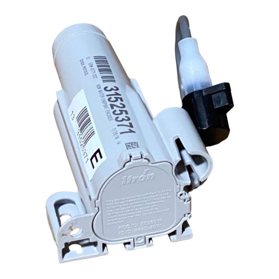
Summary of Contents for ITRON 60W Endpoint
- Page 1 Water Solutions 60W Endpoint Installation Guide Water Solutions...
- Page 2 International E-mail: support.emea@itron.com • Phone: +31 20 60 65 220 • Web Support http://eKnowledge.itron.com Itron Website http://www.itron.com Suggestions If you have comments or suggestions on how we may improve this documentation, send them to TechnicalCommunicationsManager@itron.com. 60W Endpoint Installation Guide PUB-0771-001...
- Page 3 The following documentation conventions are used in this guide: Convention Example Itron product part numbers are noted in To install the endpoint (ERW-0771-3XX), perform the parentheses. following steps. Hypertext links are in blue. See Installation Process Overview for a diagram of the installation process.
- Page 4 60W Endpoint Installation Guide PUB-0771-001...
-
Page 5: Table Of Contents
Contents Chapter 1 Before You Begin ..................7 How This Document is Organized.......................7 Chapter 2 About the 60W Endpoint ................9 Battery Life ............................9 Installation Options ..........................10 60W Startup Sequence ........................10 Installation Process Overview ......................11 Attaching a Cable Tie to the Connector ....................12 Chapter 3 Installing the 60W Endpoint .............. - Page 6 Contents 60W Endpoint Installation Guide PUB-0771-001...
-
Page 7: Chapter 1 Before You Begin
H A P T E R Before You Begin This document describes the installation of the 60W Endpoint for rod mount, wall mount, through-lid, and shelf mount installations. The 60W Endpoint is available in the following cable configurations: • Inline connector with approximately six inches of cable •... - Page 8 Chapter 1 Before You Begin 60W Endpoint Installation Guide PUB-0771-001...
-
Page 9: Chapter 2 About The 60W Endpoint
Battery Life Powered by a non-replaceable, long life dual lithium battery pack, the 60W Endpoint has an expected battery life of 20 years. Battery life is 15 years for cable lengths 150 feet and over. 60W Endpoint Installation Guide... -
Page 10: Installation Options
The 60W-R remains in Fast Transmit State for 15 minutes if no communication errors occur. 2. If the 60W Endpoint obtains register data, it remains in the Fast Transmit State for 15 minutes and moves to a Post Install State for three hours. -
Page 11: Installation Process Overview
Installation Process Overview 3. If, during the Post Install State, the register connection is interrupted or the 60W does not get three additional register reads, the 60W Endpoint reverts back to the Sleep State. 4. If register and endpoint communications are successful, the 60W Endpoint enters a Normal Operating State after the three hour period. -
Page 12: Attaching A Cable Tie To The Connector
Chapter 2 About the 60W Endpoint Attaching a Cable Tie to the Connector If the 60W Endpoint and register are not installed at the same time, secure the protective connector cover on the endpoint using a cable tie (Itron part number MSE-0005-002). Cable ties are not shipped with the 60W Endpoint, but can be ordered from Itron. -
Page 13: Chapter 3 Installing The 60W Endpoint
H A P T E R Installing the 60W Endpoint This chapter provides the instructions to install the 60W Endpoint. Select one of the following procedures: • Rod mount on page 15 • Wall mount on page 18 • Through Lid mount on page 20 •... -
Page 14: Rod Mount Installation
3/8-inch to 1/2-inch outside diameter rod (1/2-inch diameter is preferred for new installations) • Tape measure • Cutting tool to adjust rod length The 1/2-inch diameter rod hole is shown in the bottom and front view of the 60W Endpoint below. 60W Endpoint Installation Guide PUB-0771-001... - Page 15 Rod Mount Installation To install the 60W Endpoint on a rod 1. Remove the pit lid. Inspect the area to make sure there are no buried cables, pipes, or other obstructions. 2. Measure the depth of the pit box from the top of the lip (where the lid will rest) to the bottom of the pit.
- Page 16 Chapter 3 Installing the 60W Endpoint 5. Drive the rod into the ground to a depth equal to dimension A in the following illustration. • If the rod cannot be driven in enough to equal the 5 3/4 inch spacing, cut the remaining rod length to the proper height using an abrasive cut off tool.
- Page 17 7. Installation is complete when the endpoint is perpendicular to the underside of the lid. 8. The endpoint must not contact the pit structure or lid. CAUTION! If the 60W Endpoint is installed too high, too low, or is touching any of the surrounding surfaces, adjust as necessary.
-
Page 18: Wall Mount Installation
To mount the endpoint to a water pit box, select a mounting location on the inside of the pit box and try to maintain a distance of one to three inches from the bottom of the pit box lid. The endpoint is suitable for use with up to 300 feet of Itron approved cable. Required Tools and Hardware •... - Page 19 Wall Mount Installation 7. Holding the 60W Endpoint in the upright position, drill the second pilot hole. Use the bottom mounting hole as a template. NOTE! If mounting requires a screw anchor, mark the location of the bottom anchor and remove the endpoint. Drill the required mounting hole, insert the anchor, and re-attach the endpoint.
-
Page 20: Through Lid Mount
Chapter 3 Installing the 60W Endpoint Through Lid Mount This section provides instructions to mount the 60W Endpoint in a pit lid with a drilled, round 1 3/4-inch, 1 7/8-inch, or 2-inch hole. CAUTION! Some pit lids have a molded, recessed cavity that allows Itron 40W-1, 50W-1, and 50W-2 ERT modules to sit flush with the top surface of the lid. - Page 21 To install in lids with holes using the Pit Lid Mounting Kit (CFG-0771-011) page 24. This section provides the instructions to install the 60W Endpoint in a pit lid with a hole using the CFG-0771-010 Pit Lid Mounting Kit (installation with the discontinued Pit Lid Mounting Kit requires a cable tie gun).
- Page 22 Chapter 3 Installing the 60W Endpoint 5. From the bottom side of the lid, place the retainer clip collar around the retainer clip and snug the collar to the bottom side of the pit lid. Make sure the top of the retainer clip is seated against the lid surface (photo shows inverted lid material and retainer clip collar).
- Page 23 Through Lid Mount 7. Align and insert the top of the 60W Endpoint into the cavity of the retainer clip. The 60W Endpoint slides into the cavity with the Itron logo (A) and UP arrow (B) pointed to the top of the cavity circle (C). The two slots in the inner cavity circle (D) align with the back of the 60W (flat portion of the endpoint with screw holes for wall mounting - E).
- Page 24 Chapter 3 Installing the 60W Endpoint To install in lids with holes using the Pit Lid Mounting Kit (CFG-0771-011) This section provides the instructions to install the 60W Endpoint in a pit lid with a hole using the Pit Lid Mounting Kit (CFG-0771-011).
- Page 25 4. Align and insert the top of the 60W Endpoint into the cavity of the retainer clip. The 60W Endpoint slides into the cavity with the Itron logo (A) and UP arrow (B) pointed to the top of the cavity circle (C).
- Page 26 Chapter 3 Installing the 60W Endpoint 5. Tighten the retaining clip collar until the assembly is snug against the bottom of the pit lid. Pit Lid Mounting Kit installation is complete. 60W Endpoint Installation Guide PUB-0771-001...
-
Page 27: Mounting The 60W With The Passive Radiator Kit
60W Passive Radiator Kit (CFG-0771-006) Passive Radiator O-ring spacer small ring - 1 7/8" hole large ring - 2" lid hole Retainer clip Cable ties Pit lid with a pre-drilled hole (simulated pit lid material shown) 60W Endpoint 60W Endpoint Installation Guide PUB-0771-001... - Page 28 Chapter 3 Installing the 60W Endpoint Insert the passive radiator antenna, into the hole in the pit lid with the convex surface of the antenna on the top of the pit lid. The arrow on the passive radiator must point to the street.
- Page 29 5. Remove excess cable ties from assembly. 6. Align and insert the top of the 60W Endpoint into the cavity of the retainer clip. The 60W Endpoint slides into the cavity with the Itron logo (A) and UP arrow (B) pointed to the top of the cavity circle (C).
-
Page 30: Installing In A New Lid
Chapter 3 Installing the 60W Endpoint Installing in a New Lid This section describes installation of the 60W Endpoint in a pit lid without a drilled hole. NOTE! For lids with holes already drilled, see Pit Lids with Holes on page 20. -
Page 31: Shelf Mount Installation
(Inches) 6 3/4 5 3/4 Required Tools and Hardware Installing the 60W Endpoint using a shelf mount adaptor for a pit lid slot requires a Shelf Mount Adapter with Foam Spacers. • Shelf Mount Adapter (CFG-0771-007) includes foam spacers 60W Endpoint Installation Guide... - Page 32 With the foam spacer side of the adaptor up, snap the top of the 60W into the shelf mount adaptor. 2. Ensure that all 4 snap fingers are engaged in the groove around the 60W Endpoint. 3. Slide the adapter assembly into the pit lid with the foam spacers positioned on each side of the pit lid slot.
- Page 33 4. The installed position of the endpoint should be vertical and upright when the lid is replaced on the pit. CAUTION! Any endpoint position other than upright may negatively affect radio performance and battery life. 60W Endpoint Installation Guide PUB-0771-001...
- Page 34 Chapter 3 Installing the 60W Endpoint 60W Endpoint Installation Guide PUB-0771-001...
-
Page 35: Chapter 4 Connecting The 60W Endpoint
H A P T E R Connecting the 60W Endpoint This chapter provides the instructions to wire the 60W Endpoint to the water meter using an inline connector, a 5-foot cable, or a longer cable. Using an Inline Connector This section describes how to connect the 60W Endpoint to the water meter register using an inline connector assembly. -
Page 36: Using A 5-Foot Cable
Using a 5-Foot Cable This section describes how to connect the 60W Endpoint to the water meter register using the 5-foot cable. CAUTION! The wire terminations must be properly coated with a non-conductive gel material to prevent water intrusion;... - Page 37 60W Start-up Sequence and Operating Modes on page 10). In installation mode, the 60W Endpoint reads the register every 30 seconds and transmits every second for the first 15 minutes. Failure to connect to a register in the allotted time, causes the endpoint to revert back to Sleep state.
-
Page 38: Verifying Operation Of The 60W Endpoint
• ReadOne Pro, FS2PN and FS3PN readers should not be used to read the 60W Endpoint. These readers do not keep their receivers on long enough or at the right frequency to reliably capture a 60W Endpoint transmission. 60W Endpoint Installation Guide...
Need help?
Do you have a question about the 60W Endpoint and is the answer not in the manual?
Questions and answers