
Subscribe to Our Youtube Channel
Related Manuals for Fral FDHE4


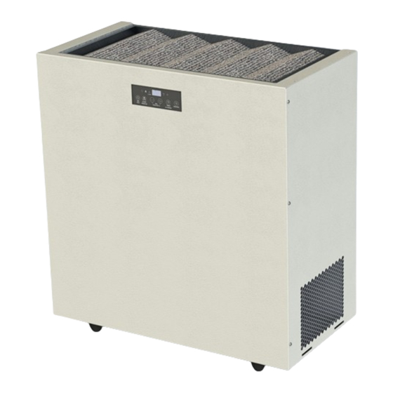
Summary of Contents for Fral FDHE4
- Page 1 DEUMIDIFICATORE DEHUMIDIFIER FDHE403 MANUALE TECNICO TECHNICAL MANUAL M.FDHE403-00 Multilanguage 17/06/2017...
- Page 2 INDICE/INDEX TECHNICAL MANUAL ............................22 SCHEMI ELETTRICI ............................... 41 ELECTRIC DIAGRAMS ............................41 M.FDHE403-00 Multilanguage 17/06/2017...
-
Page 3: Table Of Contents
MANUALE TECNICO MANUALE TECNICO .............................. 3 DICHIARAZIONE DI CONFORMITA’ ..................错 误 错 误 错 误 错 误 未 定 义 书 签 。 未 定 义 书 签 。 未 定 义 书 签 。 未 定 义 书 签 。 UTILITA’... - Page 4 Generalità ................................15 Collegamento alla rete principale ........................16 AVVIAMENTO ..............................16 CONTROLLO DI PRE AVVIAMENTO ........................16 CONTROLLO ELETTRONICO E FUNZIONAMENTO ....................17 PANNELLO DI SEGNALAZIONE E DI CONTROLLO ....................18 SMALTIMENTO DELL’UNITA’ ALLA FINE DELLA VITA ..................20 RISOLUZIONE DEI PROBLEMI ..........................
-
Page 5: Dichiarazione Di Conformita
DICHIARAZIONE DI CONFORMITÀ (Direttive comunitarie Bassa Tensione e Compatibilità elettromagnetica) FRAL Company s.r.l. Vialedell’Industria e dell’Artigianato 22/c – 35010 Carmignano di Brenta – PD – dichiara che: I deumidificatori delle serie FDHE403 soddisfano i requisiti essenziali contenuti nelle Direttive della Comunità Europea 2014/35/UE del 26 Febbraio 2014 in materia di sicurezza dei prodotti elettrici da usare in Bassa Tensione;... - Page 6 INFORMAZIONE AGLI UTENTI Ai sensi dell’art.26 del Decreto Legislativo 14 marzo 2014, n. 49 "Attuazione della direttiva 2012/19/UE sui rifiuti di apparecchiature elettriche ed elettroniche (RAEE)" Il simbolo del cassonetto sull’apparecchio o sulla sua confezione indica che il prodotto alla fine della propria vita utile deve essere raccolto...
-
Page 7: Normative Di Riferimento
ILITA’ E CONSERVAZIONE DEL MANUALE Questo Manuale è conforme ai requisiti della direttiva 2006/42/CE e successive modifiche. Il manuale fornisce tutte le indicazioni necessarie richieste per il trasporto, installazione, messa in funzione e la manutenzione delle macchine, che devono essere rigorosamente seguite da parte dell'utente per il corretto funzionamento dello stesso. - Page 8 Qualsiasi intervento sulla macchina usando qualsiasi strumento deve essere condotto solo da personale qualificato. La non osservanza delle regole riportate in questo manuale e ogni modifica fatta alla macchina senza autorizzazione esplicita, causerà l’immediata terminazione della garanzia. ATTENZIONE: prima di ogni intervento di manutenzione sull’unità deve essere fatto con l’alimentazione elettrica scollegata.
-
Page 9: Dispositivi Di Protezione Individuale
Le persone senza esperienza possono usare questa macchina solo per usi commerciali. Questa macchina deve essere sempre connessa usando spine con cavo di massa a terra come richiesto per tutte le applicazioni elettriche; FRAL Company declina ogni responsabilità per qualsiasi pericolo o danno arrecati qualora questa norma non sia rispettata. -
Page 10: Descrizione Dell'unita
DESCRIZIONE DELL’UNITA’ STRUTTURA Tutte le unità FDHE sono realizzate in lamiera zincata e verniciata con polveri poliuretaniche enamelat 180 ° C per assicurare la migliore resistenza agli agenti atmosferici. La struttura è autoportante. CIRCUITO REFRIGERANTE Il gas refrigerante utilizzato in queste unità è R410a. Il circuito frigorifero è realizzato in conformità alle ISO 97/23 in materia di procedure di saldatura e la regolamentazione PED. -
Page 11: Microprocessore
MICROPROCESSORE Il microprocessore controlla tutte le funzioni della macchina, come: il funzionamento generale, il sistema di sbrinamento automatico, allarmi e regolazione di umidità e temperatura (temperatura solo per la versione macchina con batteria ad acqua calda). RISCALDATORI ELETTRICI Resistenze elettriche da 1kW. DATI TECNICI mod. -
Page 12: Ispezione
ISPEZIONE All'atto del ricevimento dell'unità, verificarne l'integrità. La macchina ha lasciato la fabbrica in perfetto stato; eventuali danni dovranno essere immediatamente contestati al trasportatore ed annotati sul Foglio di Consegna prima di firmarlo. La nostra azienda deve essere informata, entro 8 giorni, dell'entità del danno. Il Cliente deve preparare una dichiarazione scritta di gravi danneggiamenti. -
Page 13: Spazi
SPAZI Cura assoluta deve essere prestata per assicurare un adeguato volume d'aria alla presa d'aria e scarico del ventilatore. Per questo motivo è necessario osservare le seguenti distanze (vedere le immagini riportate di seguito): lato filtro aria di aspirazione: 1 metro min. lato mandata: 1 metro min COLLEGAMENTO RACCORDO... -
Page 14: Manutenzione E Controlli Periodici
MANUTENZIONE E CONTROLLI PERIODICI AVVERTENZE IMPORTANTI Tutte le operazioni descritte in questo capitolo DEVONO ESSERE ESEGUITE SOLO DA PERSONE ESPERTE. ATTENZIONE: All'interno dell'unità sono presenti alcuni componenti in movimento. Fare molta attenzione quando si opera nelle loro vicinanze anche se l'alimentazione elettrica è... -
Page 15: Filtro Dell'aria
FILTRO DELL’ARIA Per l’ispezione e la pulizia del filtro dell’aria è sufficiente estrarre il filtro come mostrato in figura. Se necessaria è possibile lavare il filtro sotto acqua corrente; in caso di necessità di pezzi di ricambio contattare il fornitore. CONNESSIONE ELETTRICA Generalità... -
Page 16: Collegamento Alla Rete Principale
Le fluttuazioni della tensione non deve essere superiore a ± 5% del valore nominale, e lo squilibrio tra una fase e l'altra non deve superare il 2%. Se queste tolleranze non dovessero essere rispettate, si prega di contattare il nostro Studio di fornire dispositivi adeguati. -
Page 17: Controllo Elettronico E Funzionamento
La tensione deve essere quella indicata sull'etichetta dell'unità ± 5% di tolleranza. Se questo non dovesse accadere, si prega di contattare il nostro ufficio di fabbrica. Attenzione: prima di procedere alla messa in servizio, controllare che tutti i pannelli di copertura si trovino nella posizione corretta e siano bloccati con viti di fissaggio. -
Page 18: Pannello Di Segnalazione E Di Controllo
PANNELLO DI SEGNALAZIONE E DI CONTROLLO (FDHE403L11) Le unità sono dotate di pannello di segnalazione luminosa che indica i vari stati di funzionamento della macchina. Sullo stesso pannello sono presenti dei tasti che permettono di controllare e di regolare il funzionamento dell’apparecchio. - Page 19 premere uno dei tasti SET-/+: il display inizia a lampeggiare HUMIDITY/TEMPERATURE SET; per indicare il set di umidità, continuando a premere SET-/ + è possibile portare il set di umidità desiderato (da 30% a 80%). Dopo 4 secondi il display smette di lampeggiare e il nuovo set di umidità...
-
Page 20: Smaltimento Dell'unita' Alla Fine Della Vita
OSSERVANZE GENERALI E AVVISI E' buona norma eseguire controlli periodici per verificare il corretto funzionamento dell'unità: Verificare che i dispositivi di sicurezza e controllo funzionino correttamente (mensilmente). Assicurarsi che tutti i morsetti della scheda elettrica e del compressore siano ben bloccati. periodicamente i contatti mobili e fissi dei teleruttori: se vengono riscontrati danni, si prega di sostituire i contattori (mensile). -
Page 21: Risoluzione Dei Problemi
Il telaio e vari componenti, se non più utilizzabili, devono essere smontati e suddivisi secondo la loro natura, in particolare, rame e alluminio, che sono presenti in quantità nella macchina. Queste operazioni consentono un facile processo di recupero del materiale e riciclo, con riduzione dell'impatto ambientale. -
Page 22: Technical Manual
TECHNICAL MANUAL INDEX INDEX ................................22 DECLARATION OF CONFORMITY ..................错 误 错 误 错 误 错 误 未 定 义 书 签 。 未 定 义 书 签 。 未 定 义 书 签 。 未 定 义 书 签 。 UTILITY AND CONSERVATION OF THE MANUAL .................. - Page 23 AIR FILTER ............................... 34 ELECTRICAL CONNECTIONS ........................34 Generality ............................... 34 Main supply connection ......................... 35 Remote humidistat connections ......................35 START UP ..............................35 PRE-START CHECK ........................... 36 ELECTRONIC CONTROL AND FUNCTIONING ................... 36 SIGNALLING PANEL ..........................36 CONTROL PANEL ............................. 37 GENERAL OBSERVATIOTIONS AND ADVISE ....................
- Page 24 DECLARATION OF CONFORMITY (Community directives Machine Norms and Electro-magnetic Compatibility) FRAL Company s.r.l. Vialedell’Industria e dell’Artigianato 22/c – 35010 Carmignano di Brenta – PD – hereby declares that the following products: Dehumidifiers FDHE403 Series have been designed, manufactured and distributed by according to safety and electro-magnetic compatibility to European Norms and Regulations: MACHINES NORMS 2006/42/CE - 17.05.2006;...
- Page 25 UTILITY AND CONSERVATION OF THE MANUAL This Manual conforms to the requirements of the Norms 2006/42/CE and subsequent modifications. The Manual gives all necessary indications required for the transport, Installation, start-up and maintenance of the machines, which must be strictly followed by the user for a correct functioning of the same.
- Page 26 GENERAL SAFETY NORMS When installing or servicing the unit, it is necessary to strictly follow the rules reported on this manual, to conform to all the specifications of the labels on the unit, and to take any possible precautions of the case for workers.
- Page 27 People without experiences can use this machine only for a commercial use. This machine must be always connected using earthed electrical plugs as required for all electrical appliances; FRAL Company declines any responsibility for any danger or damage whenever this norm is not complied with.
- Page 28 UNIT DESCRIPTION FRAME All FDHE403 units are made from galvanised thick sheet metal, painted with polyurethane powder enamelat 180°C to ensure the best resistance against the atmospheric agents. The frame is self- supporting REFRIGERANT CIRCUIT The refrigerant gas used in these units is R410A. The refrigerant circuit is made in according to ISO 97/23 concerning welding procedures and PED regulation.
- Page 29 ELECTRIC BOX The electric switch board is made according to electromagnetic compatibility norms (2004/108 CEE) and Electrical Safety Rules for the Low Tension Appliances 2006/95 CEE. Inside the electric box there are the following components: 1. Terminals for remote control; 2.
- Page 30 TECHNICAL DATA Mod. FDHE403 Nominal power consumption at 620W 80°F-60% R.H. 115 V, 1 P, Voltage Supply 60 Hz Refrigerant charge Type R410A Quantity of refrigerant CONTROL AND SAFETY DEVICES CONTROL DEVICES All the control devices are tested on factory before the unit is delivered. Their operating mode is described in the following paragraphs.
- Page 31 INSPECTION After receiving the unit, immediately check its integrity. The unit left the factory in perfect condition; any eventual damage must be questioned to the carrier and recorded on the Delivery Note before it is signed. Our firm must be informed, within 8 days, of the extent of the damage. The Customer must prepare a written statement of any severe damage.
- Page 32 CLEARANCES Absolute care must be taken to ensure adequate air volume to the air intake and fan discharge, and to avoid air recirculation through the unit that will deeply reduce its performances. necessary to observe the following clearances (see the pictures in the following pages): - air filter suction side: 1 metre min.
- Page 33 MAINTENANCE AND PERIODIC CHECKS IMPORTANT WARNINGS All this operations described in this chapter MUST BE DONE BY TRAINED PEOPLE ONLY. WARNING: Inside the unit some moving components are present. Be very careful when operating in their surroundings even if the electric supply is disconnected. WARNING: The unit should be installed so that maintenance and/or repair services be possible.
- Page 34 AIR FILTER For the ispection and the clean of the air filter it is necessary to pull out the filter as shown in figure. If it is necessary to clean the air filter it should be clean under flowing water; in case you need spare part contact the supplier.
- Page 35 The line voltage fluctuations must not be more than ±5% of the nominal value, while the voltage unbalance between one phase and another must not exceed 2%. If those tolerances should not be respected, please contact our Firm to provide proper devices. Electric supply must be in the limits shown: in the opposite case warranty will terminate immediately.
- Page 36 This machine is designed in order to be used by experienced users or trained in shops, light industry and farms. People without experiences can use this machine only for a commercial use. PRE-START CHECK Check that all power cables are correctly connected and all terminals are fastly fixed. The voltage at the phase, must be the one indicated on the unit label ±...
- Page 37 CONTROL PANEL The Electronic card with microprocessor, control many functions: Power LED; it’s on when the machine is in the ON state. Alarm LED; it’s on when an alarm comes on. It turns off if the alarm is reset. Run LED; the LED is on when the compressor is running, blinks when the dehumidifier is waiting to restart or is in defrost.
- Page 38 GENERAL OBSERVATIOTIONS AND ADVISE It is a good rule to carry on periodic checks in order to verify the correct working of the unit: Check that safety and control devices are working correctly (monthly). Make sure that all the terminals on the electric board and on the compressor be well locked.
- Page 39 Compressor lubricating oil has to be recovered and sent to proper collecting centre; the frame and various components, if no longer usable , have to be dismantled and subdivided according to their nature; in particular, copper and aluminum, which are present in conspicuous quantity in the unit.
- Page 40 UNIT UNDER ALARM When red light is lit up, the unit is stopped and set under alarm condition. To restore normal operating mode, it is necessary to detect and remove the cause of the alarm. PROBLEM PROBABLE CAUSE and CORRECTIVE ACTION It occurs for two possible reasons: the environment temperature is too low or the defrost cycles are not able to melt the ice in the battery.
-
Page 41: Schemi Elettrici
SCHEMI ELETTRICI ELECTRIC DIAGRAMS Versione standard / Standard version M.FDHE403-00 Multilanguage 17/06/2017... - Page 42 COMPRESSORE COMPRESSOR VENTILATORE SCHEDA ELETTRONICA DI CONTROLLO ELECTRONIC BOARD SCHERMO E TASTI DI COMANDO DISPLAY AND CONTROL BUTTONS ELETTROVALVOLA SOLENOID VALVE SPINA PLUG RESISTENZA TRAY RESISTANCE TERMOSTATO E PRESSOSTATI LPS, HPS THERMOSTAT, PRESSURE SWITCH AND HIGH PRESSURE SWITCH SONDE DI TEMPERATUTA TEMPERATURE PROBE SONDA DI UMIDITA’...
Need help?
Do you have a question about the FDHE4 and is the answer not in the manual?
Questions and answers