Sign In
Upload
Manuals
Brands
Cambium Networks Manuals
Network Hardware
PTP 820E
Cambium Networks PTP 820E Manuals
Manuals and User Guides for Cambium Networks PTP 820E. We have
2
Cambium Networks PTP 820E manuals available for free PDF download: Installation Manual, Quick Installation Instructions
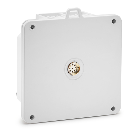
Cambium Networks PTP 820E Installation Manual (110 pages)
Brand:
Cambium Networks
| Category:
Network Hardware
| Size: 8 MB
Table of Contents
Table of Contents
3
List of Figures
6
List of Tables
8
Before You Start
9
Cross References
9
Feedback
9
Important Notes
9
Problems and Warranty
9
Purpose
9
Reporting Problems
9
Hardware Warranty
10
Repair and Service
10
Security Advice
10
Warnings, Cautions, and Notes
10
Caring for the Environment
11
Cautions
11
In EU Countries
11
Notes
11
Warnings
11
In Non-EU Countries
12
Packing
12
Pre-Installation Instructions
12
Transportation and Storage
12
Unpacking
12
Inspection
13
Figure 1: PTP 820E Rear View (Left) and Front View (Right)
14
Figure 2: Cable Gland Construction
14
Product Hardware Description
14
PTP 820E Hardware Overview
14
PTP 820E Interfaces
15
Table 1: PTP 820E Port Distribution Per Hardware Model
15
Table 2: PTP 820E Chassis Marketing Models
15
Figure 3: PTP 820E Interfaces - ESE
16
PTP 820E Interfaces - ESE
16
Figure 4: PTP 820E Interfaces - ESP
17
PTP 820E Interfaces - ESP
17
Common PTP 820E Interfaces
18
Figure 5: RSL Interface
18
Figure 6: Grounding Screw
19
Figure 7: Poe Injector
19
Poe Injector
19
Figure 8: Poe Injector Ports
20
Figure 9: Two-Wire to Poe Port Power Adaptor
20
Poe Injector Interfaces
20
Powering with External DC
20
Adaptors and Installation Kits
21
Figure 10: PTP 820E
21
Figure 11: Coupler/Splitter
21
Figure 12: OMT
21
Figure 13: Poe Injector
21
Figure 14: Twist for Coupler/Splitter
21
System Components
21
Table 3: PTP 820E Accessories
21
Table 4: Poe Injector
21
Antenna Connection
22
Power Consumption Specifications
22
Power Input Specifications
22
Power Specifications
22
Table 5: Two-Wire to Poe Port Power Adaptor
22
Environmental Specifications
23
Important Notes
23
Poe Injector Power Input
23
Power Connection Options
23
Cable Installation and Grounding
24
Figure 15: Cable Grounding Kit
24
Grounding the Cables
24
Minimum and Maximum Cable Diameter
24
Table 6: Cable Grounding Kit
24
Grounding the PTP 820E Unit
27
Power Source
28
Surge Protection
28
Available Cable Options
29
DC Cable and Connector
29
Ethernet Cable and Specifications
29
Fiber Optic Cables - Single Mode
29
Figure 16: Cable Design
30
Outdoor Ethernet Cable Specifications
30
Table 7: Ethernet Cable Color Code
30
Table 8: Outdoor Ethernet Cable Electrical Requirements
30
Outdoor DC Cable Specifications
31
Table 10: Outdoor DC Cable Electrical Requirements
31
Table 9: Outdoor Ethernet Cable Mechanical/Environmental Requirements
31
Securing the Cables
32
Special Instructions for Use of Glands
32
Table 11: Outdoor DC Cable Mechanical/Environmental Requirements
32
Table 13: Glands Kit
32
Table 14: Gland Cap
32
General Installation Procedure
33
Figure 17: Tightening the Front Portion of the Gland
37
Figure 18: Tightening the Rear Portion of the Gland
37
Connecting an Optical Fiber Cable and SFP
38
Table 15: CSFP - SFP Compatibility Example
38
Types of Sfps
38
Table 16: SFP Module Recommendations
39
Table 17: CSFP Module Recommendations
39
Table 18: SFP Module Recommendations for Third Party Equipment
39
Table 19: Approved 10 Gbe SFP+ Modules
39
Connecting Optical Fiber to Sfps
40
Connecting a DC Power Cable
45
Connecting the Ethernet Cable
48
Preparing the Ethernet Cable and Plug-In Field
48
Table 20: Materials for Preparing Ethernet Data Cables
48
Connection of Ethernet Cable to PTP 820E
51
Preparing the Ethernet Cable Already Assembled
51
Connection of Extension Cable to PTP 820E
54
Poe Injector Cable Connection
56
Poe Injector Installation and Connection
56
Poe Injector Grounding
57
Poe Injector Wall Mount Installation
57
Poe Injector Pole Mount Installation
59
Poe Injector 19" Rack Installation
60
Poe Injector ETSI Rack Installation
61
Installation Procedure and Antenna Alignment - 1+0 with 43 Dbi Flat Antenna and Standard Alignment Device (Class 2 Antennas)
64
Pole Mount Assembly and Installation
64
Figure 19: Mount Pole Mount to Pole
67
Figure 20: PTP 820E Radio with 43 Dbi Flat Antenna -Polarization Labels
68
Radio and Antenna Installation
68
Figure 21: V+45° Polarization
69
Figure 22: V-45° Polarization
69
Figure 23: V+45° Polarization (a on Top)
70
Figure 24: V-45° Polarization (B on Top)
71
Figure 25: Vertical Polarization
71
Figure 26: Complete Link - V-45° Polarization at Local Site (Left), V+45° Polarization at
72
Performing Antenna Alignment Using the Standard Alignment Kit
72
Adjusting the Antenna's Azimuth
73
Figure 27: Installation and Alignment Device - Azimuth and Elevation Adjustment Tools
75
Installation Procedure and Antenna Alignment - 1+0 with 43 Dbi Flat Antenna and Enhanced Alignment Device (Class 3 Antennas)
75
Figure 28: Installation and Alignment Device - Azimuth Range
76
Figure 29: Installation and Alignment Device - Extended Azimuth Range
77
Figure 30: Installation and Alignment Device - Delivery Elevation (45° Downward)
78
Figure 31: Installation and Alignment Device - Highest Elevation (45° Upward)
78
Pole Mount Assembly and Installation
78
Procedure
79
Wall Mount Assembly and Installation
80
Procedure
81
Attaching the PTP 820E to the Installation and Alignment Device
82
Figure 32: Horizontal Polarization - Radio and Installation and Alignment Kit
82
Figure 33: Horizontal Polarization - Screws Location
82
Adjusting the Antenna Azimuth
83
Figure 34: Vertical Polarization - Radio and Installation and Alignment Kit
83
Figure 35: Vertical Polarization - Screws Location
83
Performing Antenna Alignment Using the Enhanced Alignment Kit
83
Figure 36: Azimuth Screws - Top View (Azimuth 45° to the Right)
87
Figure 37: Removing the Azimuth Screws (Side View)
87
Figure 38: Azimuth Screws in New Placement - Top View (Azimuth 45° to the Right)
88
Adjusting the Antenna Elevation
89
Figure 39: Repositioning the Azimuth Screws (Side View)
89
Direct Mount Configurations
92
Figure 40: Horizontal / Vertical Pole
93
1 +0 Direct Mount Installation
92
2 +0 Single Polarization
96
Figure 41: Horizontal Polarization
97
Figure 42: Vertical Polarization
97
2+0 Dual Polarization
99
Multiband Configurations
101
Multiband with PTP 820E and PTP 820C with 2+0 Single Polarization
101
Table 21: Multiband Antenna Marketing Model
101
Multiband with PTP 820E and PTP 820C with 2+0 Dual Polarization
105
Multiband with PTP 820E and 1+0 PTP 820S
107
Figure 43: PTP 820Stwist Orientation
109
Advertisement
Cambium Networks PTP 820E Quick Installation Instructions (16 pages)
System Release 10.9
Brand:
Cambium Networks
| Category:
Conference System
| Size: 2 MB
Advertisement
Related Products
Cambium Networks PTP 500 Series
Cambium Networks PTP 300 Series
Cambium Networks PTP 820G
Cambium Networks PTP 850E
Cambium Networks PTP 820F
Cambium Networks PTP 820 Series
Cambium Networks PTP 820S Assured
Cambium Networks PTP 820C
Cambium Networks PTP 820C HP
Cambium Networks PTP 820S
Cambium Networks Categories
Wireless Access Point
Network Hardware
Network Router
Switch
Wireless Router
More Cambium Networks Manuals
Login
Sign In
OR
Sign in with Facebook
Sign in with Google
Upload manual
Upload from disk
Upload from URL