Table of Contents
Advertisement
Quick Links
Advertisement
Table of Contents

Subscribe to Our Youtube Channel
Related Manuals for Cambium Networks TD-90 Series


Summary of Contents for Cambium Networks TD-90 Series
- Page 1 USER GUIDE TD-90 Series...
- Page 2 Accuracy While reasonable efforts have been made to assure the accuracy of this document, Cambium Networks assumes no liability resulting from any inaccuracies or omissions in this document, or from use of the information obtained herein. Cambium reserves the right to make changes to any products described...
-
Page 3: Table Of Contents
Contents Contents Overview Overview and TD-90 modes of operation Mode 3 operation (Default) Mode 2 operation Mode 1 operation TD-90 Pre-Configuration Pre-Config requirements Mode 2/3 (Default mode) Prerequisite for operation Pre-Config requirements Mode 1 Prerequisite for operation Pre-Config instructions for Modes 1, 2 and 3 Quick steps for deployment TD-90 Mechanical and Electrical Interfaces TD-90 Base Mount Surface and Dimensions... - Page 4 TD-90 Errors System Recovery Contacting Cambium Networks...
-
Page 5: Overview
Overview This document provides pre-configuration set-up and operational instructions for the Cambium TD-90 antenna positioner. The positioner is designed to work with Cambium based Point to Point and point to multi-point solutions. This manual uses the Cambium PTP 700 series with integrated antenna to illustrate setup and operation. -
Page 6: Overview And Td-90 Modes Of Operation
Overview and TD-90 modes of operation The TD-90 has three modes of operation identified as Mode 1, Mode 2, and Mode 3. All three modes provide automated alignment and require different levels of configuration. The TD-90 software is designed to default to Mode 3 if mode 1 is not defined and use mode 2 if GPS targeting data is available. A high-level description is provided below followed by a step by step walk through of each mode. -
Page 7: Mode 2 Operation
Slave 1 peak: Waits for Master command to move, performs first step peak function, reports peak complete back to master. Master 2 peak: Master performs final step peak function. Slave 2 peak: Waits for Master command to move, performs second step peak function, reports peak complete back to master. - Page 8 Master 1 Scan Align: 90° scan with 5° steps and 5 second dwell time. The Master records signal strength levels at all 18 steps and returns to the highest recorded level. Slave 1 Scan Align: Waits for Master command to move, 90° scan with 5° steps and 5 second dwell time.
-
Page 9: Pre-Configuration
TD-90 Pre-Configuration The TD- 90 is designed to be pre- configured before deployment to allow for auto acquisition once installed in the field. Follow the steps outlined in this section to pre-configure your TD-90 for deployment. Pre-Config requirements Mode 2/3 (Default mode) Prerequisite for operation ... - Page 10 Figure 1 : Step 1 - Setup of TD-90 to pre-configure Step 2 Using a Laptop computer, open your Network and Sharing Center as shown below and select Change adapter settings on the upper left-hand side as highlighted below. Figure 2 : Step 2 - Change adapter settings TD-90 Pre-Configuration...
- Page 11 Step 3 Select Local Area Connection as highlighted below. Step 3 - Local Area Connection Figure 3 : Step 4 Select Properties as highlighted below Figure 4 : Step 4 - Select “Properties” Step 5 Select Internet Protocol Version 4 (TCP/IPv4) by doubling clicking over it (as highlighted below) TD-90 Pre-Configuration...
- Page 12 Figure 5 : Step 5 - Select Internet Protocol Version 4 (TCP/IPv4) Step 6 1. Select Use the following IP address. 2. Assign your computer a 169.254.1.102 IP address and a subnet mask of 255.255.255.0 as shown below. 3. Click OK after complete and close all network windows. Step 6 - IP and Subnet Mask Settings Figure 6 : TD-90 Pre-Configuration...
- Page 13 Step 7 Open a Google Chrome or Mozilla Firefox browser and type the default IP address 169.254.1.245 and the TD-90 home page will open to the System Summary. Figure 7 : Step 7 - Home page with System Summary Step 8 Select Setup on the left side menu to display the System Setup table.
- Page 14 Figure 8 : Step 8 - System Setup page Step 9 For Mode 2 and 3 operations, enter in a valid IP Address, Subnet Mask, Gateway for the TD-90. Followed by the IP address for the radio. Example shown below identifies the 4 fields. Figure 9 : Step 9 - Mode 2 and 3 setup requirements Step 10 (Optional Mode 1 setup)
- Page 15 Figure 10 : Step 10 - Optional Mode 1 Setup TD-90 Pre-Configuration...
-
Page 16: Quick Steps For Deployment
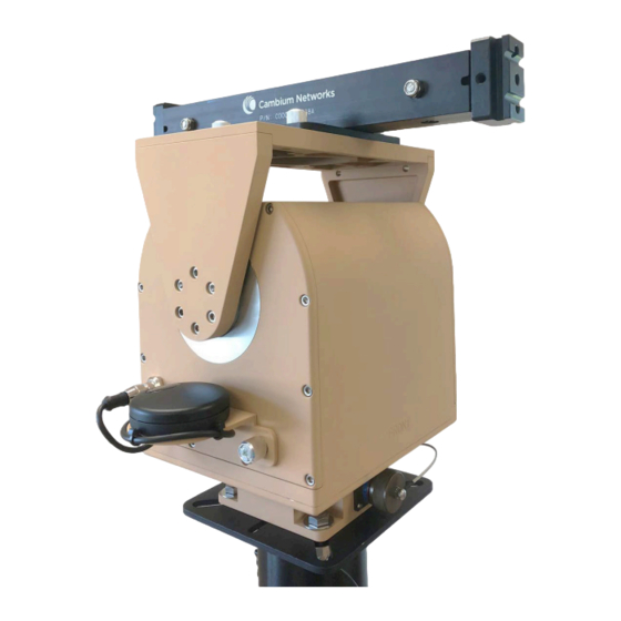
Quick steps for deployment The Quick steps to operation section provides the essential steps to get your TD-90 up an operational. Follow the step by step directions below and refer to the other sections of the manual for a more detailed review of operation. ... - Page 17 Figure 2 : Step 2 - TD-90 with antenna adapter bracket Step 3 - Mount Cambium Radio Mount the Cambium Radio to the antenna adapter bracket by sliding the radio adapter end into the antenna mount bracket. Be sure to place the radio on the side marked “Front” and pin the radio to the bracket using the captive pin.
- Page 18 Plug Breakout end of cable labeled “PSU” into Power Injector port labeled “ODU” Note Plug Cambium Networks Power Injectors into AC or DC source Connection C: FROM TD-90 Power Injector port labeled “LAN” port TO Ethernet switch Connection D: FROM PSU Power Injector port labeled “LAN” port TO Ethernet switch Connection E: Connection E is optional for monitoring purposes.
- Page 19 establishment to take place. See TD-90 Pre-Config instructions for more details. Figure 5 : Step 5- From – To connection diagram Step 6 - Power Up Once power is applied at each PoE injector, both the radio and the TD-90 will boot up. An orange LED will indicate link activity between the TD-90 and the radio followed by a solid green LED to indicate the TD-90 controller is up.
-
Page 20: Mechanical And Electrical Interfaces
TD-90 Mechanical and Electrical Interfaces The TD-90 is a two axis mechanical rotating positioner with an embedded controller that communicates with the radio and drives the antenna to automate the process of establishing the line of sight radio link. The TD-90 requires some mechanical and electrical setup in order for this process to be successful. This section details the TD-90 base mount and antenna mount surfaces along with identifying each connector, its purpose, and the individual pinouts. ... -
Page 21: Td Interface Details
Figure 2 : Antenna mount surface with dimensioned hole pattern TD Interface Details The images and tables in this section identifies interfaces on all 4 sides of the TD-90. TD-90 Mechanical and Electrical Interfaces... - Page 22 Front View of TD-90 Figure 3 : Front View of TD-90 Callout Description “Front” surface to identify the side the antenna mounts. The TD- 90 built in compass is referenced to this surface. Optional DC power input. Accepts 24-52VDC input. 5 Pin male connector part number D38999/20WD5PN.
-
Page 23: Left Side View Of
Left Side View of TD-90 Figure 5 : Left Side View of TD-90 Callout Description GPS Connector. Allows connection to removable GPS provided with the system. Pinout provided below. Removable GPS antenna puck. Provides local coordinates to TD-90 positioner. Figure 6 : Connector Pinout for GPS input TD-90 Mechanical and Electrical Interfaces... -
Page 24: Rear View Of
Pin No. Description Signal Ground +5VDC power RS-232 Rx RS-232 Tx +12VDC (not used) Rear View of TD-90 TD-90 Mechanical and Electrical Interfaces... - Page 25 Callout Description Azimuth manual drive access cap. Requires 5/16 inch socket to remove cap and expose manual drive shaft. 5/16 inch socket also drives the manual shaft. Elevation manual drive access cap. Requires 5/16 inch socket to remove cap and expose manual drive shaft.
-
Page 26: Right Side View Of
Right Side View of TD-90 TD-90 Mechanical and Electrical Interfaces... - Page 27 Callout Description Upper ground stud. Above azimuth ¼ -20 inch ground stud passes to below azimuth ¼ -20 inch ground stud. Power and Status LED indicator. Solid green = Power on and normal operation, slow blink (2Hz) = waiting for connection to radio, fast blink = Error The Primary S U (PSU) is the Ethernet pass-thru connector for the Cambium radio that provides a connection point for the radio above the azimuth axis of rotation.
- Page 28 Pass through Pinouts for AUX Ethernet PSU Ethernet Pass-thru TD-90 Data and Power (37 Description (Sealed RJ-45) Pin D38999) Transmit + Transmit - Receive + PoE 48-56VDC PoE 48-56VDC Receive - PoE Rtn PoE Rtn TD-90 Mechanical and Electrical Interfaces...
-
Page 29: Web Based User Interface
Web Based User Interface The Cambium Networks TD-90 web based user interface provides control and status pages for a user to pre-configure the system for operation, monitor the system status, and/or perform manual control of the system. This section provides screen shots and details the six available control or status pages on the TD- 90 user interface. - Page 30 Home Page Descriptions Callout Description Default IP address for Cambium TD-90. IP address may be changed on the Setup page Displays the current software revision loaded on the TD-90 embedded controller. The “STOP” button will appear when the system is in a “Run” state. Clicking over the “STOP”...
- Page 31 Home Page Descriptions Callout Description The Remote Side table is only active when a radio link is established. The remote side table provides details of the TD-90 and radio on the opposite end of the link. A separate table is provided below with additional details on the Remote Side table.
- Page 32 System Summary Attributes Description Positioner TD-90 positioner may be named to identify as a unique name. The TD-90 may be Name named under the Positioner Config page under “Unit Name” Positioner Identifies the unique serial number assigned to the TD-90 Serial Number Positioner...
- Page 33 System Summary Attributes Description Latitude Displays current angular distance North or South of the earths equator. North of equator = Positive and South of equator = Negative Longitude Displays current angular distance east or west of the meridian at Greenwich UK Altitude Distance in meters above sea level Radio / Tracking...
-
Page 34: Setup
Remote Side Attributes Description Remote Remote side status of TD-90 positioner state. State Remote Geodetic Position Azimuth Displays the remote side TD-90’s Azimuth angle is Geodetic frame which is the TD-90’s Azimuth with reference to true north. Elevation Displays the remote side TD-90’s Elevation angle with reference to Geodetic frame (±30 from Horizon) Latitude Displays the remote side TD-90 current angular distance North or South of the earths... - Page 35 Web Based User Interface...
- Page 36 Setup Page Descriptions Callout Description The System Setup table provides a single table to walk users through a TD-90 setup for Modes 1, 2, or 3 operations. The TD90 IP Interface allows the TD-90 IP Address, Subnet Mask, and Gateway address to be updated The Radio Interface is the location to enter the IP address of the radio that is planned for deployment with the TD-90.
-
Page 37: Manual Control
TD-90 Manual Control The TD-90 Manual Control page provides a tool to manually move a TD-90 positioner by slewing around or commanding to a specific azimuth and elevation. The callout’s below point to the various controls that are unique to the Manual Control page and are described in the table below. -
Page 38: Positioner Config
Manual Control Page Descriptions Callout Description The Slew Controls allow a user to slew a TD-90 Up, Down, Left, or Right using the arrow buttons The Geodetic position displays the Azimuth and Elevation with reference to True North = 0 Azimuth and Horizon = 0 Elevation The Pedestal position displays the pedestal angles with reference to the TD-90 center of travel in both axis = to 0... - Page 39 Web Based User Interface...
-
Page 40: Snmp V1 And V2C
Positioner Config Page Descriptions Callout Description The Limits are set to default maximum travel range a TD-90 do (Shown above ±200° Azimuth and ±30° Elevation). The user may limit the travel range within this Azimuth or Elevation range The stow position is default to 0 degrees azimuth and 0 degrees elevation. The unit will move to the user entered preset when the “Stow”... - Page 41 Web Based User Interface...
- Page 42 Current SNMP Configuration Callout Description The default page displayed under the SNMP tab is the Current SNMP configuration settings. Here you will find if the SNMP agent is currently enabled or disabled, the SNMP version and community string. The “Continue to SNMP Wizard” button launches a new page to start the SNMP configuration process.
- Page 43 SNMP Config Callout Description SNMP Agent State allows the user to turn on (Enabled) or turn off (Disabled) the SNMP agent. Version allows the user to select what version of SNMP they wish to run. v1 has plaintext community string with 32 bit counters v2c has plaintext community string with support for 64 bit counters, and v3 which adds encryption and authentication to 64 bit counters.
-
Page 44: Snmp V3
Confirm SNMP Configuration Callout Description The Confirm SNMP Configuration shall display the current selected configuration for user review before accepting and changing the SNMP Configuration. The “Change SNMP Configuration” button will save the selections made during the setup wizard. TD-90 SNMP v3 The SNMP v3 wizard adds authentication and encryption. - Page 45 Current SNMP Configuration Callout Description The first three fields list the current status of the SNMP agent. The SNMP Agent State is either turned on “Enabled” or turned off “Disabled”. The SNMP Version shows the user the current version in operation. For this section that covers v3 only the version should always indicate v3.
- Page 46 Web Based User Interface...
- Page 47 SNMP Config Callout Description The SNMP Agent State allows the user to turn on “Enabled” or turn off “Disabled” the SNMP agent The Version field allows the user to select the version to run. Since this section covers v3 setup the version should be set to v3. SNMP Engine ID Format allows selection between MAC address, IPv4 Address or text string to identify the unique entity.
- Page 48 Web Based User Interface...
- Page 49 SNMP User Policy Configuration Callout Description The System Admin Policy provides controls for the user to select the authentication and privacy policies for the Administrator. Select between security levels of No Authentication and No Privacy, Authentication and No privacy, or Authentication and Privacy. Based on your selection the system will also allow you to pick the Hash type to be used for Authentication (MD5 or SHA-1) and the Privacy Protocol (DES or AES-128).
- Page 50 SNMP User Policy Configuration Callout Description User edited field to enter the name to be used for your user account User selectable field to identify to the positioner which SNMP user is the local Cambium radio Drop-down to select System Administrator, Read Only, or Disabled Authentication Password field.
-
Page 51: Compass
Confirm SNMP Configuration Callout Description The Confirm SNMP Configuration shall display the current selected configuration for user review before accepting and changing the SNMP Configuration. System Administrator settings allows review of selections made before accepting changes Read only settings allows review of selections made before accepting changes The user field allows review of users that have been setup during the configuration. - Page 52 Web Based User Interface...
- Page 53 Compass Page Descriptions Attributes Description Heading Displays the current heading from the last time the compass was read. Each time the TD- 90 is commanded to move it reads the compass to get a reference to current heading Compass Displays the raw output from the compass Sensor Read Allows the user to take an instant read from the compass sensor.
- Page 54 Web Based User Interface...
- Page 55 Error Error Description Possible Fixes 0x00000001 RADIO_ CONNECT_ ERR: Connection between TD- 90 and Check IP local radio settings on Radio and TD- 90. Is the TD-90 and the Radio on the same network? Is the cable between the Radio and TD-90 in place? Check all Ethernet cabling...
- Page 56 Error Error Description Possible Fixes 0x00000020 AZ_SCAN_MOVE_TIMEOUT ERR: Link is down after TD-90 Distant end of has concluded an azimuth only scan and returned to the link has moved highest reported signal level or power has been removed from distant end 0x00000040 LINK_DOWN_STEP_START_ERR: Radio link lost during one Check power to...
- Page 57 Error Error Description Possible Fixes 0x00001000 DATABR_DOWN_STEP_ERR: Link goes down during one of Recoverable the steps in acquisition process error. System will alert of link outage, wait for radio link to recover and 0x00002000 RADIO_DISCONNECT_ERR: Connection between TD-90 and Check Ethernet Radio is lost cabling between radio and TD-...
- Page 58 Error Error Description Possible Fixes 0x00020000 MODE1_DATABR_DROP_ERR: Data bridge drops after it has Recoverable been established but before the scan and peak process. error. Indicates excessive compass or GPS error. TD-90 will default to Mode 0x00040000 MULTIPT_REPOSITION_ERR: Positoiner found link, started Check target scan and failed to regain connection end radio for...
- Page 59 Error Error Description Possible Fixes 0x00400000 TARGET_ CMD_ INTERNAL_ ERR: Internal message error Radio data setting target coordinates after sweep in mode 1 or 2 bridge connection is marginal and was not able to successfully pass data to each side for local coordinates.
- Page 60 Error Error Description Possible Fixes 0x02000000 MODE2_DATABR_DROP_ERR: TD- 90 selects mode 2 and Recoverable exchanges coordinate locations on both ends. TD-90’s both error. Suggests point using on board compass. It is assumed a data bridge that GPS or will be active after the aid of GPS and compass pointing. If Compass may not bridge exists the system will default back to mode 3 to establish link.
- Page 61 System Recovery In case that the user forget about the login credential or IP address. Use the following steps to recover the unit into factory default mode: 1. Default boot procedure: Power up – (within 10 seconds) –Power down – (within 10 seconds)—Power up.
- Page 62 Contacting Cambium Networks Product Details https://www.cambiumnetworks.com/products/wifi/ Quick Start Guide https://www.cambiumnetworks.com/products/wifi/ User Guide https://support.cambiumnetworks.com/files/r-series/ Release Notes https://support.cambiumnetworks.com/files/r-series/ Software Resources https://support.cambiumnetworks.com/files/r-series/ Knowledge Base (KB) https://help.cambiumnetworks.com/hc/en-us/sections/206524647- Articles cnPilot-R-series-R201-R201P- Community http://community.cambiumnetworks.com/t5/cnPilot-R-Series-Home- Small/bd-p/cnPilot Support https://www.cambiumnetworks.com/support/ Warranty https://www.cambiumnetworks.com/support/warranty/ Repair Queries https://support.cambiumnetworks.com Feedback For feedback, e-mail to support@cambiumnetworks.com/...
Need help?
Do you have a question about the TD-90 Series and is the answer not in the manual?
Questions and answers