
Related Manuals for Side-Power SE 60/185 S2


Summary of Contents for Side-Power SE 60/185 S2
- Page 1 SE 60/185 S2 SIDE-POWER Thruster Systems Installation Manual & User Manual SLEIPNER MOTOR AS P.O. Box 519 N-1612 Fredrikstad Norway Document id: 5693 www.side-power.com Revision: Date: 2019 © Sleipner Motor AS 2019...
-
Page 2: Table Of Contents
Wiring Diagram ..............11-12 Control Panel Installation............13 Checklist for DC and IP Thrusters ........... 14 Important Thruster User Considerations and Precautions ..15 How to use Side-Power thrusters ..........16 Maintenance ................17 Trouble shooting SE ..............18 Warranty statement ..............19 Parts List.................. -
Page 3: Technical Specifications
Schutz, wenn der Propeller blockiert ist. Nach der driveshaft protects electromotor and gear system Integrated microprocessor monitors solenoids, letzten Benutzung schaltet das Original Side-Power if propeller gets jammed. reducing wear and risk of solenoid lock-in. Auto- Panel automatisch nach 6 Minuten ab. Der integrierte... -
Page 4: Planning & Important Precautions
S-link control system without the designated and approved interface will render all warranties and responsibilities for the complete line of Side-Power products connected void and null. If you are interfacing by agreement with Sleipner and through a designated Side-Power supplied interface, you are still required to also install at least one original Side-Power control panel to enable effi... -
Page 5: Gear Leg & Motor Bracket Installation
BOATS 2 - 4 CENTRELINE BOATS CENTRELINE Ø 8.5 mm 0.33” TUNNEL CENTRELINE TUNNEL CENTRELINE Ø 28.5 mm Ø 23mm 1.1” 0.91” Apply MS Polymer sealant or equal to both sides of the gasket Measure the drive shaft has come through the motor bracket at the correct height with the template enclosed Fasten bolts... -
Page 6: Propeller Installation
drive pin propeller washer lock nut Anode Anode holding screw MG_0028 Propeller Installation MC_0018 ! Please refer to the graphic for special considerations relating to your model ! Centre the drive pin on the propeller shaft and rotate the shaft, so the pin is in a horizontal state. Insert the propeller onto the shaft and rotate the propeller until the drive pin aligns into the slot/ groove in the propeller. -
Page 7: Motor Installation
2 - 3 Drive pin Turn gear leg shaft so the motor coupling Motor coupling will fit Coupling Gasket Bottom Fasten bolts 17Nm (12,4lb/ft) MG_0029 Motor Installation MC_0043 ! Please refer to the graphic for special considerations relating to your model ! Insert drive pin on the motor shaft and insert the coupling to the motor shaft. -
Page 8: Thruster Electrical Installation
Fuse Main switch Battery Thuster 12V or Motor Tighten to Lugs 15Nm/ 11lb/ft Tighten to IMPORTANT 15Nm/ 11lb/ft Do NOT use washers between lugs and terminals, this can cause overheating. Washers must be placed in the outer position before tightening nut. washers MG_0019 Thruster Electrical Installation... -
Page 9: Electrical Specifications
Electrical Specifi cations MC_0044 SE60/185 S2 5693 2019... -
Page 10: Control Panel Cable Installation
SIDE-POWER ‘on-off’ control panel (Direction) (ON) Timer Option: Automatic main switch. connects the battery to the thruster. Operated from the control panel(s). Requires 5-lead control cables. Thuster Motor Ext. cable Y cable Ext. cable 4- or 5-lead 4- or 5-lead... -
Page 11: Wiring Diagram
With Automatic Main Switch: 6 1278-xxM 5-LEAD CONTROL CABLE 6 1278-xxM 5-LEAD CONTROL CABLE STERN 6 1265 5-LEAD Y-CONNECTOR 6 1265 5-LEAD Y-CONNECTOR STERN Switch Switch STERN 5A fuse 5A fuse 6 1278-xxM 5-LEAD 6 1278-xxM 5-LEAD CONTROL CABLE CONTROL CABLE 6 1277-xxM 4-LEAD 10A fuse 6 1277-xxM 4-LEAD... - Page 12 NB! Make sure to not use any electro- nic interface box (delay box) older than the 6 1232i (ex. 6 122x) MG_0032 SE60/185 S2 5693 2019...
-
Page 13: Control Panel Installation
CONTROL PANEL TEMPLATES For control panels 8950 / 8960 61,1mm For control panels 8950 / 8960 Cut out area: Ø 51,8 mm / 2" Cut out area: Ø 51,8 mm / 2" Ø52 This way Up! Ø 3,0 mm / 0,12" Ø... -
Page 14: Checklist For Dc And Ip Thrusters
Checklist for DC and IP Thrusters MC_0033 ..Propeller is fastened correctly to the shaft... Propeller turns freely in tunnel... The anode holding screw is tightened well with thread glue... Anti-fouling have been applied to the gearhouse and propeller but NOT on the anode or the gearhouse lid where the propeller is fastened. -
Page 15: Important Thruster User Considerations And Precautions
Important Thruster User Considerations and Precautions MC_0004 • Ensure you know the location of the main battery switch that disconnects the thruster from all power sources (batteries) so the thruster can be turned off in case of a malfunction. • Always turn the main power switch off before touching any part of the thruster, as an incidental start while touching moving parts can cause serious injuries. -
Page 16: How To Use Side-Power Thrusters
Turn boat to starboard Turn boat to starboard (Stern) Bow+Stern Thruster How to use Side-Power thrusters How to use a bowthruster 1. Turn main power switch for the bowthruster on. (Always turn off the main power switch when not onboard.) 2. -
Page 17: Maintenance
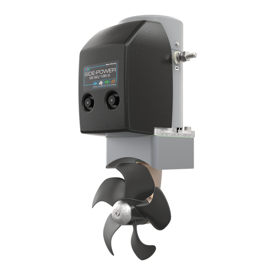
Electromotor Directional solenoids Motorbracket for holding motor and gearhouse together on the tunnel. Breakpin secures the electromotor if propeller is jammed. Changeable from inside the boat. 5-blade skew propeller for ultimate performance. Prefilled lifetime lubricated gearhouse. Changeable anode protects gear-house from corrosion in seawater. -
Page 18: Trouble Shooting Se
Trouble shooting SE Before seeking assistance at the help desk of your Side-Power dealer/distributor please perform these tests and make notes of all measurements to ensure that they have as much information as possible to work on. NB! All check points and solutions must be carried out after consulting the relevant information elsewhere in this manual to un- der-stand how the system is intended to work. -
Page 19: Warranty Statement
Warranty statement 1. The equipment manufactured by Sleipner Motor AS (The “Warrantor”) is warranted to be free from defects in workmanship and materials under normal use and service. 2. This Warranty is in eff ect for of two years (Leisure Use) or one year (Commercial use) from the date of purchase by the user. Proof of purchase must be included, to establish that it is inside the warranty period. -
Page 20: Parts List
Spare Parts MC_0024 For the most up to date documentation, we advise you to visit our website www.side-power.com and locate your products relevant spare parts list. Warranty statement MC_0024 1. The equipment manufactured by Sleipner Motor AS (The “Warrantor”) is warranted to be free from defects in workmanship and materials under normal use and service. - Page 21 Notes MC_0037 ..............................................................................................................................................................................................................................................................................................................................................................................................................................................................................................................................................................................................................................................................................................................................................................................................................................................................................................................................................................................................................................................................................................................................................................................................................................................................................................................................................................................................................................................................................................................................................................................................................................................................SE60/185 S2 5693 2019...
- Page 22 Notes MC_0037 ..............................................................................................................................................................................................................................................................................................................................................................................................................................................................................................................................................................................................................................................................................................................................................................................................................................................................................................................................................................................................................................................................................................................................................................................................................................................................................................................................................................................................................................................................................................................................................................................................................................................................SE60/185 S2 5693 2019...
- Page 23 Notes MC_0037 ..............................................................................................................................................................................................................................................................................................................................................................................................................................................................................................................................................................................................................................................................................................................................................................................................................................................................................................................................................................................................................................................................................................................................................................................................................................................................................................................................................................................................................................................................................................................................................................................................................................................................SE60/185 S2 5693 2019...
- Page 24 Worldwide sales and service www.side-power.com SLEIPNER MOTOR AS P.O. Box 519 N-1612 Fredrikstad Norway The information given in the document was correct at the time it was published. However, Sleipner Motor AS can not accept liability for any inaccuracies or omissions it may contain.
Need help?
Do you have a question about the SE 60/185 S2 and is the answer not in the manual?
Questions and answers