MTS Sensors Level Plus M Series Replacement Manual
Liquid-level sensors, digital output, transmitter electronics
Hide thumbs
Also See for Level Plus M Series:
- Operation and installation manual (44 pages) ,
- Operation and installation manual (51 pages)
Advertisement
Quick Links
Transmitter Electronics Replacement Guide
Guide overview
This guide contains software setup and digital component replace-
ment procedures for the MTS M-Series Model MG digital transmitter
(gauge). Software setup screens shown in this guide are Modbus
examples. If you are installing DDA setup software, your setup screens
will be similar.
Software and hardware requirements
MTS Part Numbers:
625051 - M-Series PC Setup Modbus Software CD and RS-485 to
RS-232 Adapter
625052 - M-Series Digital PC Setup Modbus Software CD
380075 - RS-485 to RS-232 Adapter
625053 - M-Series Digital PC Setup (DDA)
Technical support and shipping information
The M-Series transmitter design is modular in nature. The electronics
can be replaced in the field without on-site support of the MTS Service
Department.
Ordering information and software updates:
You can get the latest ordering information and software updates by
using the World Wide Web. Go to www.mtssensors.com.
Technical support
Phone: 800-633-7609
E-mail: levelplus@mts.com
Shipping address
MTS Systems Corporation
Sensors Division
3001 Sheldon Drive
Cary, North Carolina 27513
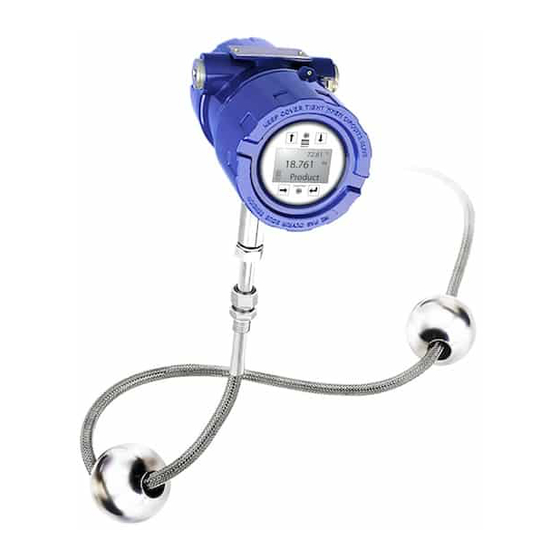
Level Plus
Liquid-Level Sensors
M-Series
Model MG
Digital Output
M-Series Model MG
digital transmitter
®
Contents
Guide overview
„
Software and hardware requirements
„
Technical support and shipping information
„
Notices used in this guide
„
Related publications
„
Before you begin
„
Software installation and configuration; Modbus and DDA
„
Transmitter electronics replacement procedures
„
Installing current parameters
„
Notices used in this guide
Notes
These notices provide important tips, guidance, or advice.
Caution
These notices indicate situations that can be potentially hazardous to
you. A Caution notice is placed just before a description of a potentially
hazardous procedure, step, or situation.
Attention
These notices indicate possible damage to devices or data. An
Attention notice is placed before the instruction or situation in which
damage could occur.
Always follow applicable local and national electrical codes and
observe polarity when making electrical connections. Do not remove
cover or make electrical connections to the M-Series transmitter with
power turned on. Make sure that no wire strands are loose or sticking
out of the terminal block connection which could short and cause a
problem.
Related publications
The following publications are available in Adobe Acrobat Portable
Document Format (PDF) at http://www.mtssensors.com.
550731 - Installation sheet, M-Series Electronics Module
550784 - Product Specification, Level Plus M-Series Digital
550537 - Product Specification, Level Plus M-Series Floats and
Accessories
All specifications are subject to change. Contact MTS for specifications that are critical to
your application. Go to www.mtssensors.com for the latest support documentation.
SENSORS
551104 A
Advertisement

Related Manuals for MTS Sensors Level Plus M Series


Summary of Contents for MTS Sensors Level Plus M Series
- Page 1 Level Plus ® Liquid-Level Sensors SENSORS M-Series Model MG Digital Output 551104 A Transmitter Electronics Replacement Guide Contents Guide overview „ Software and hardware requirements „ Technical support and shipping information „ Notices used in this guide „ Related publications „...
- Page 2 Type in a filename such as ModbusRestore or DDARestore and path that you can easily locate. then, click “Save” Figure 1. Shortcut creation and Target entry M-Series Model MG Digital Gauge, Transmitter Electronics - Replacement Guide 551104 A MTS Sensors...
- Page 3 (Figure 4). Plug the wired connector into the PC board terminal block. Reattach the transmitter instrument housing cover. Figure 4. Top electronics board retaining screw locations MTS Sensors M-Series Model MG Digital Gauge, Transmitter Electronics - Replacement Guide 551104 A...
- Page 4 Continue with “Replacing the transmitter electronics boards”. Figure 8. Removing the retaining clip from inside of the pipe assembly M-Series Model MG Digital Gauge, Transmitter Electronics - Replacement Guide 551104 A MTS Sensors...
- Page 5 Factory” tab. The Factory Tab window opens. Type the Gradient value you recorded from the Gradient Off Tag (Figure 11). Figure 11. Factory window; Entering the new gradient value and reading new settings MTS Sensors M-Series Model MG Digital Gauge, Transmitter Electronics - Replacement Guide 551104 A...
- Page 6 Printed in USA. Copyright © 2007 MTS Systems Corporation. All Rights Reserved in all media. UNITED STATES GERMANY JAPAN MTS Systems Corporation MTS Sensor Technologie MTS Sensors Technology Sensors Division GmbH & Co. KG Corporation SENSORS 3001 Sheldon Drive Auf dem Schüffel 9 Ushikubo Bldg.
Need help?
Do you have a question about the Level Plus M Series and is the answer not in the manual?
Questions and answers