Table of Contents
Advertisement
Quick Links
A52x Series Electronic Refrigeration Controller with
Adaptive Defrost
Technical Bulletin
Introduction
This document describes the features and functions of the A52x Electronic Refrigeration Controller with Adaptive
Defrost (A52x Controller), and provides guidelines and instructions to set up, adjust, and troubleshoot the
controller.
Overview
IMPORTANT: Use of this product is subject to and constitutes your agreement to the End User License
Agreement set forth at www.johnsoncontrols.com/buildings/legal/digital LIT No. 12012405.
IMPORTANT: Use this A52x Refrigeration Controller only as an operating control. Where failure or malfunction
of the A52x Controller could lead to personal injury or property damage to the controlled equipment or other
property, additional precautions must be designed into the control system. Incorporate and maintain other
devices, such as supervisory or alarm systems or safety or limit controls, intended to warn of or protect against
failure or malfunction of the A52x Controller.
IMPORTANT : Utiliser ce A52x Refrigeration Controller uniquement en tant que dispositif de contrôle de
fonctionnement. Lorsqu'une défaillance ou un dysfonctionnement du A52x Régulateur risque de provoquer des
blessures ou d'endommager l'équipement contrôlé ou un autre équipement, la conception du système de
contrôle doit intégrer des dispositifs de protection supplémentaires. Veiller dans ce cas à intégrer de façon
permanente d'autres dispositifs, tels que des systèmes de supervision ou d'alarme, ou des dispositifs de
sécurité ou de limitation, ayant une fonction d'avertissement ou de protection en cas de défaillance ou de
dysfonctionnement du A52x Régulateur.
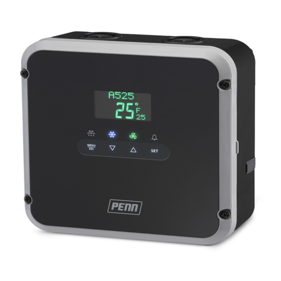
The A52x Controller provides refrigerated space control and defrost control for medium and low-temperature
refrigeration applications. The A525 Controller has five line-voltage relays to control the compressor, defrost
functions, high and low speed evaporator fans, and user-provided alarms. The controller can also control the
following functions:
•
Resistive heat
•
Hot-gas bypass
•
Off-cycle defrost
•
Two-speed evaporator fans
Refer to the A524/A525 Series Refrigeration Controller with Adaptive Defrost Installation Instructions (Part No. 24-
7664-3310) for information about relay wiring. The adaptive defrost feature adjusts the defrost schedule to the
minimum number of defrost intervals required to maintain peak efficiency, save energy, and maintain consistent
space temperature. The A52x Controller has an IP65 enclosure with holes in the enclosure base for wall-surface
mounting. An optional DIN Rail mounting kit (Part No. BKT524-1K) is also available.
A52x Series Electronic Refrigeration Controller with Adaptive Defrost Technical Bulletin
1
LIT No. 12012405
Issued April 2018
Advertisement
Table of Contents

Subscribe to Our Youtube Channel
Related Manuals for Penn A52 Series


Summary of Contents for Penn A52 Series
- Page 1 A52x Series Electronic Refrigeration Controller with Adaptive Defrost LIT No. 12012405 Technical Bulletin Issued April 2018 Introduction This document describes the features and functions of the A52x Electronic Refrigeration Controller with Adaptive Defrost (A52x Controller), and provides guidelines and instructions to set up, adjust, and troubleshoot the controller.
-
Page 2: A52X User Interface
Concepts A52x User Interface The A52x Controller has an LCD user interface with adjustable brightness that displays the system status and setup information. Four status indicator icons that show the defrost, cooling, evaporator fan, and alarm features provide a visual indication of the system status and alarms. You can use four touchpad keys to navigate the system and to see detailed system information, change parameter settings, and respond to system alarms.The defrost and alarm icons also function as touchpad keys to initiate unscheduled defrost cycles and clear system alarms. - Page 3 Figure 2: A52x Display Fields, Icons, and Touchpad Keys Table 1: A52x Controller Icons, Keys, Description, Behavior, and User Actions Callout Item Name Description / Behavior / User-Actions Defrost Icon The Defrost icon indicates the status of the defrost relay. A lit icon indicates that the defrost relay is closed and the system is in defrost mode.
- Page 4 RS485 The RS485 Modbus communications terminal block is restricted to the 0.20 to 0.30 mm MODBUS optional PENN Precision Superheat Controller (PSHC). Do not connect (26 to 22 AWG) any other Modbus device to these terminals. Stranded wires and twisted-leads RS485 Modbus signal common or reference.
-
Page 5: Refrigeration Mode
Figure 4: A52x Controller High Voltage Terminal Block Connections Table 3: A52x Controller High Voltage Terminal Blocks, Terminals, and Wire Sizes Terminal Terminal Description, Function, and Requirements Recommended Block Label Voltages Wire Sizes 90-240 VAC Two terminals for supply power connection to the A525 Controller. 0.75 to 2.50 mm Requires 90 to 240 VAC;... -
Page 6: Defrost Mode
• The fan icon indicates the evaporator fan relay status, which is either on or off. • The defrost relay and icon remain off. • The refrigeration icon indicates when the compressor is running. • The LCD user interface displays the Home screen, which shows the system name, date, time, space temperature, and set point. -
Page 7: Defrost Types
A defrost duration is the time period that the refrigeration system is in defrost mode and the system is melting ice off of the evaporator coil. The defrost duration may include Drip Time. A defrost interval is defined as the time between the start of a defrost cycle and the start of the next defrost cycle. -
Page 8: Defrost Schedule Types
Time Based Defrost Termination Time-based defrost control terminates the defrost duration when the user-defined maximum defrost duration elapses. The defrost duration must be of sufficient length to remove all of the ice that accumulated on the evaporator during the previous defrost interval. Timed Defrost Termination does not require a defrost termination sensor or switch. - Page 9 • Evaporator Fan Drip-Time Delay • Evaporator Fan Temperature Delay • Evaporator Fan Time Delay When the A52x Controller is in a delay period, the delay type and the minutes left in the delay scroll across the Message Field at the top of the display. Anti-Short Cycle Delay Anti-Short Cycle Delay (ASD) maintains the compressor relay off or open for a period of time after the relay cycles off.
-
Page 10: System Setup Parameters
Figure 8: Example of the A52x Controller Relay States During Defrost Duration, Drip Time Delay, and Evaporator Fan Delay TIME Compressor Relay Load Demand Satisfied Defrost Relay LO/AUX (Fan) Relay Drip Time Evap Fan Delay Defrost Normal Cooling Delay (Cool Down) Duration Mode Defrost... -
Page 11: Evaporator Fan Control
HI-SPD relay, the LO-SPD/AUX relay is available to control an auxiliary device. QREV/PSHC Setup The A52x Controller is designed to communicate with the Johnson Control/PENN Quick Response Expansion Valve (QREV) and Precision Super Heat Controller (PSHC). If the refrigeration system uses a QREV/PSHC, you can monitor the QREV status, adjust the superheat set point, and change the refrigerant type on the PSHC to match the refrigeration system’s refrigerant type. - Page 12 Figure 9: Compressor and Lo/Aux Relay States for Single Speed Evaporator Fan Operation in Normal Refrigeration Mode: Continuous On Fan or Cycling Fan with Compressor Time Compressor Relay HI-SPD Relay 1-Speed Evap Fan (On Continuous) HI-SPD Relay 1-Speed Evap Fan (Cycles with Com pressor Relay) Figure 10: Compressor, Lo/Aux, and Hi-Spd Relay States for Two Speed Evaporator Fan Operation in...
-
Page 13: Adaptive Defrost Setup Parameters
Evaporator Fan Operation in Defrost Mode The Evaporator Fan Drip-Time Delay, Evaporator Fan Temperature Delay, and Evaporator Fan Time Delay settings affect the behavior of the Evaporator Fan in defrost mode and post-defrost mode. You can set up the post-defrost evaporator fan behavior with the Evaporator Fan Delay After Defrost feature. -
Page 14: Universal Inputs And Alarms
Universal Inputs and Alarms Universal Input Modes You can set each of the universal inputs to one of the modes in Table 5. When you select an input mode, one or more control actions become associated with that mode. Note: The system defines alarm actions separately from control actions. -
Page 15: Cooling Shutdown
Alarm Setup Parameters Table 7: List of Alarms and Alarm True Conditions Alarms Alarm TRUE Condition High Temperature Alarm The Sensor 1 temperature is greater than the high temperature alarm value that you defined for a period of time equal to or greater than the alarm delay. Low Temperature Alarm The Sensor 1 temperature is less than the low temperature alarm value that you defined for a period of time equal to or greater than the alarm delay. -
Page 16: System Shutdown
System Shutdown A system shutdown takes priority over the normal control of the compressor, defrost, and fan relays. It can happen if an alarmed condition such as man-in room, refrigerant leak or emergency switch is activated. An active system shutdown state means that all outputs are set to off, excluding the alarm output. This state can be entered by detection of a refrigerant leak, if enabled, or a Universal Input that is configured to provide this signal. -
Page 17: Navigating The High-Level Status And Setup Start Screen
Navigating the High-Level Status and Setup Start Screen To scroll through the high-level Status and Setup Start screens, tap the DOWN and UP keys. The WELCOME screen displays when the A52x Controller powers on, and then changes to WELCOME TO A525 the HOME screen. -
Page 18: Viewing System Status
Viewing System Status The SYSTEM STATUS screens provide the current status of the sensors, the cooling system, the universal inputs, and the system control relays. The SYSTEM STATUS screens also identify the firmware versions on the controller. The information on these screens can help you to troubleshoot system and controller problems. To scroll through the SYSTEM STATUS screens, tap the DOWN and UP keys. -
Page 19: Viewing Qrev/Pshc Status
Viewing QREV/PSHC Status Note: The following QREV/PSHC STATUS screens are only available if you connect a QREV/PSHC to the controller and set up the interface. The A52x Controller can monitor and control a QREV/PSHC. To view the QREV/PSHC STATUS screens, navigate to the QREV/PSHC STATUS start screen in the high-level menu flow and press SET to go to the QREV/PSHC: SUPERHEAT status screen. -
Page 20: Setting Up The System Setup Screens
Setting Up the System Setup Screens The first step to configure the A52x Controller is to define your refrigeration system in the System Setup screens. You can set up the following settings in the System Setup Screens: • System time and date •... - Page 21 Setting Up the System Time and Date To set the date and time on the A52x Controller, navigate to the SYSTEM SETUP start screen and press SET to go to the DATE/TIME screen. To scroll through the DATE/TIME screens and options, tap the DOWN and UP keys. SYSTEM SETUP DATE/TIME TIME FORMAT...
- Page 22 Setting Up the System Components To define the sensors, evaporator fan motors, defrost system type, and defrost termination type on the controller, navigate to the high-level SYSTEM SETUP screen and press SET. To scroll through the SYSTEM COMPONENT screens and options, tap the DOWN and UP keys. Note: The selections you make in the following setup screens determine many of the setup screens that appear on the REFRIGERATION SETUP and DEFROST SETUP menu flows.
- Page 23 Setting Up the System Setup Parameters To set the system setup parameters, navigate to the high-level SYSTEM SETUP screen and press SET to go to the SYSTEM SETUP menu.To scroll through the SYSTEM SETUP screens and options, tap the DOWN and UP keys. SYSTEM SETUP DATE/TIME In the DATE/TIME setup start screen, tap the DOWN and UP keys to scroll to the...
-
Page 24: Setting Up The Refrigeration Setup Screens
Setting Up the Refrigeration Setup Screens To enter the REFRIGERATION SETUP menu, navigate to the high-level REFRIGERATION SETUP screen, and press SET. To scroll through the Refrigeration Setup screens and options, tap the DOWN and UP keys. REFRIGERATION SETUP SETPOINT SETPOINT To set the setpoint, select the setpoint value and press SET. -
Page 25: Setting Up The Defrost Cycle
Setting Up the Defrost Cycle To enter the Defrost Setup menu, navigate to the high-level DEFROST SETUP screen and press SET. To scroll through the DEFROST SETUP screens and options, tap the DOWN and UP keys. DEFROST SETUP To set the maximum defrost duration time, select the maximum defrost duration value and press SET. -
Page 26: Setting Up The Defrost Schedule
Setting up the Defrost Schedule To enter the Defrost Schedule menu, navigate to the high-level DEFROST SETUP screens and press SET. To scroll through the DEFROST SETUP screens and options, tap the DOWN and UP keys. Note: To automatically schedule the defrost cycles to start at equal intervals after the first defrost time, select AUTOMA (Automatic) in the DEFROST SCHEDULE screen. -
Page 27: Setting Up Adaptive Defrost
Setting Up Adaptive Defrost To enter the Adaptive Defrost menu, navigate to the high-level DEFROST SETUP screens and press SET. To scroll through the DEFROST SETUP screens and options, tap the DOWN and UP keys. Note: To enable the ADAPTIVE DEFROST setup start screen, set the Defrost Termination type to TEMP or HVBIN in the DEFROST TERM TYPE screen in the System Setup menu flow. -
Page 28: Setting Up The Universal Inputs
Setting Up the Universal Inputs To view the Universal Inputs screens, navigate to the UNIVERSAL INPUTS start screen and press SET to go to the UI4 screen. To scroll through the universal inputs screens and option, tap the DOWN and UP keys. UNIVERSAL INPUTS UI 4... - Page 29 Setting Up the Alarm Setup 1 of 2 To view the Alarm Setup screens, navigate to the ALARM SETUP start screen and press SET to go to the Sn1: HIGH TEMP ALARM screen. To scroll through the alarm setup screens, tap the DOWN and UP keys. ALARM SETUP To enable the high temperature alarm at Sensor 1, select YES and press SN1: HIGH...
- Page 30 Setting Up the Alarm Setup 2 of 2 Note: If you select Door Open (DOR OPN), Man in Room (MAN RM), Refrigerant Leak (REF LK), or Emergency Switch (EMG SW) for the UI4 and UI5 input alarms, the following menu displays. If you select None (NONE) for the UI4 and UI5 input alarms, the following menu does not display.
-
Page 31: File System
File System To access the File system, navigate to the FILE start screen and press SET to enter the File menu. To scroll through the FILE screens, tap the DOWN and UP keys. FILE CONFIG FILE INSERT USB To begin a config file export , select YES, press SET, CONFIG FILE EXPORT DRIVE... - Page 32 A524/A525 Controller Screens Table 8 shows the screens that you may see as you set up the A52x Controller for your refrigeration system. You can view the black screens in Table 8 in the A52x Controller user interface. The gray screens appear when they are relevant to your selections in the System Setup and other setup screens.
- Page 33 Table 8: A52x Controller Set Up Screens, Descriptions, Behaviors, Value Ranges a Selection Lists (Part 2 of 19) Screen Name in Parameter Description, Behavior, User Action Value Range or Default Message Field Selection List Value or Selection The status of the user-supplied high-voltage, binary input switch OPN or CLS connected to the HV/BIN terminals displays in the upper Info field.
- Page 34 Table 8: A52x Controller Set Up Screens, Descriptions, Behaviors, Value Ranges a Selection Lists (Part 3 of 19) Screen Name in Parameter Description, Behavior, User Action Value Range or Default Message Field Selection List Value or Selection Displays the current calculated Superheat temperature value. To No selection scroll through the QREV/PSHC Status screens, tap the DOWN or QREV/PSHC:...
- Page 35 Table 8: A52x Controller Set Up Screens, Descriptions, Behaviors, Value Ranges a Selection Lists (Part 4 of 19) Screen Name in Parameter Description, Behavior, User Action Value Range or Default Message Field Selection List Value or Selection The time format options are 12 hour or 24 hour. 12H or 24H To save the selection and go to TIME , press SET.
- Page 36 Table 8: A52x Controller Set Up Screens, Descriptions, Behaviors, Value Ranges a Selection Lists (Part 5 of 19) Screen Name in Parameter Description, Behavior, User Action Value Range or Default Message Field Selection List Value or Selection To set the day, select the day value and press SET. Day value Auto Daylight Saving start screen.
- Page 37 Table 8: A52x Controller Set Up Screens, Descriptions, Behaviors, Value Ranges a Selection Lists (Part 6 of 19) Screen Name in Parameter Description, Behavior, User Action Value Range or Default Message Field Selection List Value or Selection Select the preferred sensor or no sensor. To save the selection, A99 , NTC, or press SET.
- Page 38 Table 8: A52x Controller Set Up Screens, Descriptions, Behaviors, Value Ranges a Selection Lists (Part 7 of 19) Screen Name in Parameter Description, Behavior, User Action Value Range or Default Message Field Selection List Value or Selection QREV/PSHC Setup Screens To scroll through the system setup start screens, tap the DOWN No selection or UP keys.
- Page 39 Table 8: A52x Controller Set Up Screens, Descriptions, Behaviors, Value Ranges a Selection Lists (Part 8 of 19) Screen Name in Parameter Description, Behavior, User Action Value Range or Default Message Field Selection List Value or Selection To go to the DISPLAY BRIGHTNESS screen, press SET . No selection DISPLAY BRIGHTNESS...
- Page 40 Table 8: A52x Controller Set Up Screens, Descriptions, Behaviors, Value Ranges a Selection Lists (Part 9 of 19) Screen Name in Parameter Description, Behavior, User Action Value Range or Default Message Field Selection List Value or Selection To scroll through the REFRIGERATION SETUP start screens, tap No selection the DOWN or UP keys .
- Page 41 Table 8: A52x Controller Set Up Screens, Descriptions, Behaviors, Value Ranges a Selection Lists (Part 10 of 19) Screen Name in Parameter Description, Behavior, User Action Value Range or Default Message Field Selection List Value or Selection Select the evaporator fan speed when the compressor relay is off. For 1-SPD Fan: To save the selection, press SET.
- Page 42 Table 8: A52x Controller Set Up Screens, Descriptions, Behaviors, Value Ranges a Selection Lists (Part 11 of 19) Screen Name in Parameter Description, Behavior, User Action Value Range or Default Message Field Selection List Value or Selection See Evaporator Fan Temperature Delay No selection To go to the EVAPORATOR FAN DELAY TEMPERATURE EVAP FAN DELAY...
- Page 43 Table 8: A52x Controller Set Up Screens, Descriptions, Behaviors, Value Ranges a Selection Lists (Part 12 of 19) Screen Name in Parameter Description, Behavior, User Action Value Range or Default Message Field Selection List Value or Selection Enter the real-time value at which the first defrost cycle begins. To Real-time value save the value, press SET.
- Page 44 Table 8: A52x Controller Set Up Screens, Descriptions, Behaviors, Value Ranges a Selection Lists (Part 13 of 19) Screen Name in Parameter Description, Behavior, User Action Value Range or Default Message Field Selection List Value or Selection To go to the MAX TIME BETWEEN DEFROST screen to set the No selection maximum time between defrosts, press SET .
- Page 45 Table 8: A52x Controller Set Up Screens, Descriptions, Behaviors, Value Ranges a Selection Lists (Part 14 of 19) Screen Name in Parameter Description, Behavior, User Action Value Range or Default Message Field Selection List Value or Selection To erase the Adaptive Defrost feature’s historical data and YES or NO reset the system to the initial defrost interval, select YES RESET...
- Page 46 Table 8: A52x Controller Set Up Screens, Descriptions, Behaviors, Value Ranges a Selection Lists (Part 15 of 19) Screen Name in Parameter Description, Behavior, User Action Value Range or Default Message Field Selection List Value or Selection To set an action mode for UI4, select NORMAL , COO OFF (Cool NORMAL, COO Off), or AUX ON (Auxiliary On), and press SET.
- Page 47 Table 8: A52x Controller Set Up Screens, Descriptions, Behaviors, Value Ranges a Selection Lists (Part 16 of 19) Screen Name in Parameter Description, Behavior, User Action Value Range or Default Message Field Selection List Value or Selection To set an action mode for UI5, select NORMAL , COO OFF (Cool NORMAL, COO Off), or AUX ON (Auxiliary On), and press SET.
- Page 48 Table 8: A52x Controller Set Up Screens, Descriptions, Behaviors, Value Ranges a Selection Lists (Part 17 of 19) Screen Name in Parameter Description, Behavior, User Action Value Range or Default Message Field Selection List Value or Selection To set the Sensor 1: High Temperature Alarm threshold, select -40F°...
- Page 49 Table 8: A52x Controller Set Up Screens, Descriptions, Behaviors, Value Ranges a Selection Lists (Part 18 of 19) Screen Name in Parameter Description, Behavior, User Action Value Range or Default Message Field Selection List Value or Selection To set the Sensor 1: High Temperature Alarm realarm interval, 0 to 99 minutes select the time period value and press SET .
- Page 50 Table 8: A52x Controller Set Up Screens, Descriptions, Behaviors, Value Ranges a Selection Lists (Part 19 of 19) Screen Name in Parameter Description, Behavior, User Action Value Range or Default Message Field Selection List Value or Selection DATA EXPORT To set up a data export in the DATA EXPORT screen, press SET . No selection DATA EXPORT To confirm a data export, select YES , and press SET .
-
Page 51: Info Field Codes
Info Field Codes The two information fields in the lower right corner of the LCD display flashing codes in the parameter selection screens. Table 9 identifies and describes these codes. Use the up and down arrows to scroll through the available selections in the screen. - Page 52 Table 9: Information Field Selection Codes, Code Identifications, and Code Descriptions Info Field Code Identification and Description Selection Codes Hot Gas defrost Select to choose a defrost type in the SYSTEM SETUP screens. High Voltage Binary Switch A defrost termination type when a high-voltage binary switch terminates the defrost Select to operate a two-speed fan at low speed.
-
Page 53: Relay Electrical Ratings
Related Documentation Technical Specifications Relay Electrical Ratings Table 10 through Table 14 provides the electrical ratings for the control relays in the A52x Controller. See Table 16 for the relay’s duty cycle ratings. Table 10: SPST Compressor Relay Electrical Ratings Agency and File UL 60730 EN 60730... - Page 54 Table 13: SPST High Speed Fan (HI_SPD) Relay Electrical Ratings Agency and File UL 60730 EN 60730 Applied AC Voltage at 50/ 24 VAC 120 VAC 240 VAC 240 VAC 60 Hz Horsepower 1/2 HP 1/2 HP 1/2 HP Full Load Amperes 9.8 A 4.9 A 4.9 A...
- Page 55 Table 15: (Part 2 of 2)A52x Refrigeration Controller with Adaptive Defrost Product A524/A525 United States: cULus Listed; UL60730-1, UL60730-2-9, File SDFY.SA515; Compliance FCC Compliant to CFR47, Part 15, Class B Canada: cULus Listed; CAN/CSA-E60730-1:15, CAN/CSA-E60730-2-9:15, File SDFY7.SA516; Industry Canada (IC) compliant to Canadian ICES-003, Class B Europe: CE Mark –...
-
Page 56: North American Emissions Compliance
Building Technologies & Solutions 507 E. Michigan Street, Milwaukee, WI 53202 ® Johnson Controls and PENN are registered trademarks of Johnson Controls in the United States of America and/or other countries. All other trademarks used herein are the property of their respective owners. © Copyright 2018 by Johnson Controls. All rights reserved.
Need help?
Do you have a question about the A52 Series and is the answer not in the manual?
Questions and answers