Penn A421 Series Installation Manual
Standard electronic temperature controls
Hide thumbs
Also See for A421 Series:
- Installation manual (29 pages) ,
- Installation instructions manual (20 pages) ,
- Installation manual (13 pages)
Table of Contents
Advertisement
Applications
Important: Use this A421 Series Electronic
Temperature Control only as an operating control.
Where failure or malfunction of the A421 Control
could lead to personal injury or property damage
to the controlled equipment or other property,
additional precautions must be designed into the
control system. Incorporate and maintain other
devices, such as supervisory or alarm systems or
safety or limit controls, intended to warn of or
protect against failure or malfunction of the A421
Control.
Important: Utiliser ce A421 Series Electronic
Temperature Control uniquement en tant que
dispositif de régulation. Lorsqu'une défaillance
ou un dysfonctionnement du A421 Control risque
de provoquer des blessures ou d'endommager
l'équipement contrôlé ou un autre équipement, la
conception du système de contrôle doit intégrer des
dispositifs de protection supplémentaires. Veiller
dans ce cas à intégrer de façon permanente d'autres
dispositifs, tels que des systèmes de supervision
ou d'alarme, ou des dispositifs de sécurité ou de
limitation, ayant une fonction d'avertissement
ou de protection en cas de défaillance ou de
dysfonctionnement du A421 Control.
Dimensions
Figure 1: A421 Control with Type 1 (NEMA), IP20
enclosure dimensions, in. (mm)
A421 Series Standard Electronic Temperature
Controls Installation Guide
Figure 2: A421 Control with Type 4X (NEMA), IP66
enclosure dimensions, in. (mm)
Parts included
Each A421 Control includes a Johnson Controls
PENN
A99 Series temperature sensor. Refer to
®
Temperature Sensors
documentation for details.
A99 Series Temperature Sensors
The A421 Controls require an A99 sensor, and each A421
Control includes an A99 sensor. Any A99 Series sensor
works with the A421 Series Controls. Do not replace an
A99 Series sensor with any other brand, series, or type
of temperature sensor. See
available A99 Series sensor models.
You can extend the sensor leads in the field. See Table
1 for information about wire sizes and lengths. On
long sensor cable runs, use shielded cable to reduce
electromagnetic interference (EMI). Observe EMI best
practices when you route sensor leads.
Do not completely immerse the A99 Series sensors in
water or any other liquid. The A99 sensors are moisture
tolerant and splash resistant but if you immerse the
sensor, liquid can enter the sensor probe where the steel
tube meets the wire cable and result in sensor failure,
which voids any warranty.
Part No. 24-7664-3019 Rev. E
2019-10-14
or
®
A99 Series
Ordering information
for
A421ABC, A421AEC, A421GBF,
A421GEF
Advertisement
Table of Contents

Related Manuals for Penn A421 Series


Summary of Contents for Penn A421 Series
- Page 1 The A421 Controls require an A99 sensor, and each A421 Control includes an A99 sensor. Any A99 Series sensor works with the A421 Series Controls. Do not replace an A99 Series sensor with any other brand, series, or type of temperature sensor. See Ordering information available A99 Series sensor models.
-
Page 2: Additional Guidelines For Mounting Type 4X/Ip66 Controls
Mounting a Type 1/IP20 control on DIN rail Provide a section of 35 mm DIN rail that is longer than the control width. Mount the DIN rail in a suitable location and use appropriate mounting hardware. A421 Series Standard Electronic Temperature Controls Installation Guide... - Page 3 Contact with components carrying Observe the following guidelines, procedures, and hazardous voltage can cause electric shock and may illustrations when you wire an A421 Series Control and A99 result in severe personal injury or death. Series sensor. • Select the appropriate A99 sensors for the ambient operating range that the A421 Control monitors and controls, as shown in Table 7.
- Page 4 L2 supply power connection for 208/240 VAC supply power Figure 4: Wiring the A421 Series Controls using the applications through the jumper same power source to power the control operation and from LC. (Figure 4).
-
Page 5: Setup And Adjustments
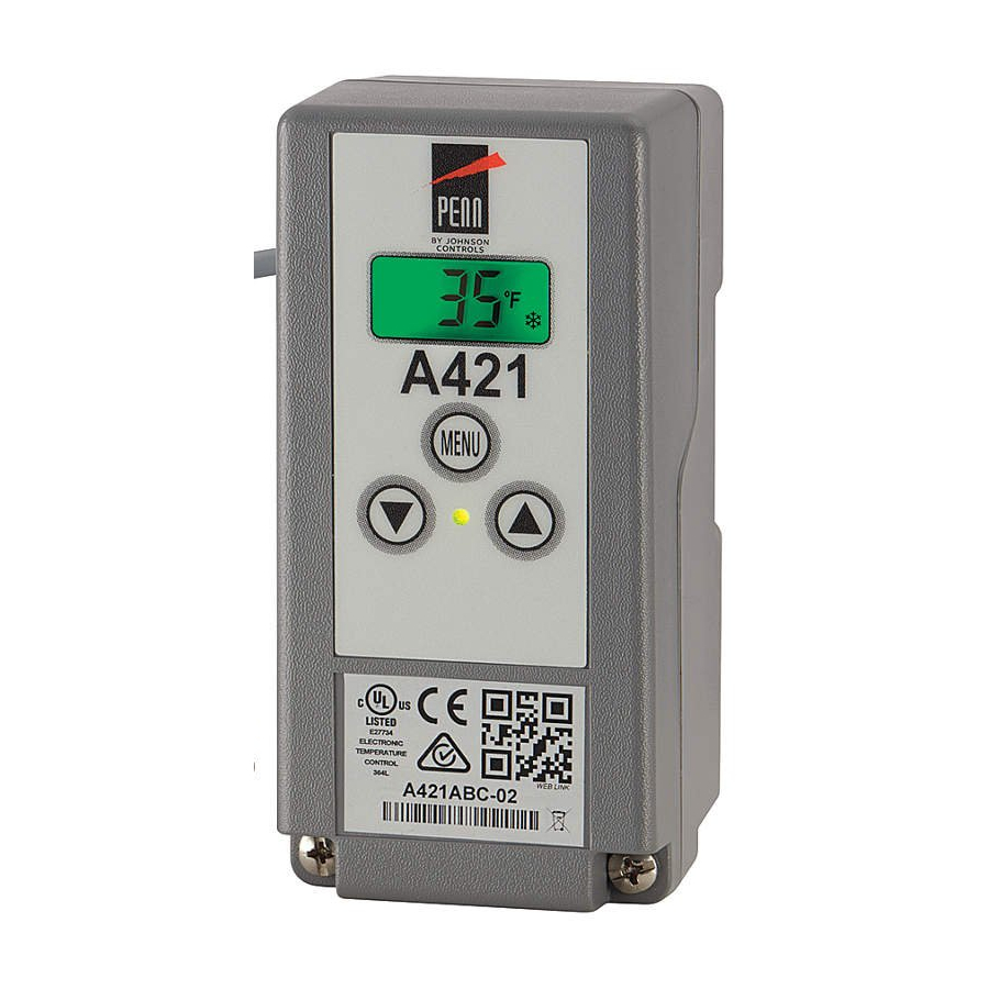
• OFF > On = Heating mode = Flame icon • OFF < On = Cooling mode = Snowflake icon The A421 Series Control has a backlit LCD screen (Figure 5). You can adjust the LCD brightness. During normal operation, the LCD displays the Main screen, which provides the following information: •... - Page 6 Select either the Fahrenheit (°F) or sensor. Select a temperature value to offset the Celsius (°C) temperature scale. temperature displayed on the LCD from the temperature sensed at the sensor. The sensor A421 Series Standard Electronic Temperature Controls Installation Guide...
-
Page 7: A421 Control Parameter Setup Menus
Main screen. Basic menu Use the Basic menu to quickly edit the On and OFF temperature values, as well as the Sensor Failure Mode (SF) and the Anti-Short Cycle Delay (ASd) value. A421 Series Standard Electronic Temperature Controls Installation Guide... -
Page 8: Advanced Menu
With the current parameter value displayed, press • Temperature Units (Un) Down or Up to scroll through all of the parameter code’s usable values and display the preferred value. • Temperature Setback (tSb) A421 Series Standard Electronic Temperature Controls Installation Guide... -
Page 9: Restricting User Adjustment
To make sure that the A421 is not in restricted mode, position the jumper on both pins. See Figure 10. Select the OFF and On values that define the application’s required control band (Figure 9). A421 Series Standard Electronic Temperature Controls Installation Guide... -
Page 10: Troubleshooting
If Troubleshooting sensor wiring is correct, replace the sensor. Figure 12: Temperature versus sensor resistance A421 Series Controls display fault codes on the LCD as described in the following table. Table 5: Fault codes Fault code Definition... -
Page 11: Repair Information
Ordering information Control: Type 4X (NEMA), IP66 watertight enclosure for surface-mount applications. See Table 6 for information about a standard A421 Series Rated for 24 VAC Class 2, safety extra low Electronic Temperature Control. See Table 7 and Table voltage. Includes an A99BB-25C temperature 8 to order A99 sensors, mounting hardware, and other sensor with 9 7/8 in. -
Page 12: Technical Specifications
Two end clamps for DIN rail sections Voltage Directive. A99-CLP-1 Surface mounting clip for A99B and A99C Australia and New Zealand: RCM, Series Temperature Sensors Australia/NZ Emissions Compliant SHL10-603R Sun shield for A99B and A99C Series Temperature Sensors A421 Series Standard Electronic Temperature Controls Installation Guide... -
Page 13: North American Emissions Compliance
• Increase the separation between the equipment and receiver. • Connect the equipment into an outlet on a circuit different from that to which the receiver is connected. • Consult the dealer or an experienced radio/TV technician for help. A421 Series Standard Electronic Temperature Controls Installation Guide... - Page 14 Canada This Class (B) digital apparatus meets all the requirements of the Canadian Interference-Causing Equipment Regulations. Cet appareil numérique de la Classe (B) respecte toutes les exigences du Règlement sur le matériel brouilleur du Canada. Single point of contact APAC Europe NA/SA JOHNSON CONTROLS...
Need help?
Do you have a question about the A421 Series and is the answer not in the manual?
Questions and answers