Table of Contents
Advertisement
Quick Links
Applications
A11 Series low temperature cutout controls are available
with single-pole, single-throw (SPST) or single-pole,
double-throw (SPDT) contact action. Applications include
the sensing of low temperature conditions to avoid
overcooling or icing of hydronic coils, cooling coils, and
liquid handling pipes. The controls are compact and
sturdy, and have an adjustable temperature setpoint
range with a fixed differential. You can access the range
adjustment screw at the bottom of the control, or at the
top of the control when you remove the cover.
Important: All A11 Series coil temperature controls
are designed for use only as operating controls.
Where an operating control failure would result
in personal injury and/or loss of property, it is
the responsibility of the installer to add devices
(safety, limit controls) or systems (alarm, supervisory
systems) that protect against, or warn of, control
failure.
Required tools
Use the following tools to install the control:
• 1/2 in. (1.3 cm) electrical metallic tubing (EMT) bender
• Hole saw
• Tin snips or hack saw
• Vise
• Brackets
• 4 in. (10.1 cm) electrical box covers with a center hole
knockout, or T-752-1001 1/2 in. (1.3 cm) duct flanges
• Nylon tie wraps with holes
• 1/2 in. (1.3 cm) EMT connectors
• 1/4 in. (6.4 mm) poly tubing
• Copper tubing
• EMT or Unistrut
• Conduit hangers or Minerallac straps
• Self-tapping sheet metal screws
• Machine screws and nuts
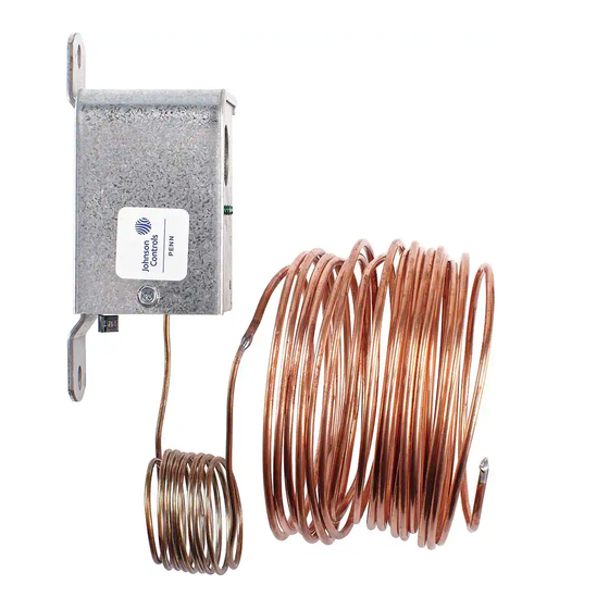
• A11 Low Temperature Cutout Control
• Element mounting bracket
A11 Series Low Temperature Cutout Control
Mounting
Before you begin:
Do not install A11 controls where the ambient
temperature at the control exceeds 140°F (60°C), or
falls below 0°F (-18°C). Make sure that the maximum
temperature at the sensing bulb does not exceed 250°F
(121°C).
1.
Locate the sensing element on the downstream
side of the coil. Expose the element to all areas
where low temperatures may occur.
2.
Horizontally serpentine the 20 ft (6.1 m) long
sensing element across the face of the coil to sense
temperatures in all areas.
Ensure that the horizontal pitch of the coil does
not exceed 5° (one in. per ft) for the areas that you
want to protect. See Figure 1.
Mounting considerations
The primary purpose of a low limit cutout is to prevent a
coil from freezing. Before you mount the control, consider
the following factors:
• It is vital that you protect the lower 6 in. (15.20 cm) of
the coil, because cool air drops to the bottom of the
coil.
• If the tubes in the coil freeze, the coil can crack and
leak. As water leaks from the coil, the control system
may sense the reduced water pressure and increase the
flow of water to compensate for the loss, which causes
even more damage.
• It is important to follow all instructions to install low
limit controls because the low limit controls incorporate
a vapor-charged sensing element. The vapor in the
element creates a change in pressure with a change
in temperature within the sensing element, eventually
causing the electrical switch in the device to open or
close.
• The size of the duct work or air handling unit system in
which you install the device may require more than one
low limit control to adequately protect the entire coil.
• System accessibility affects how you mount the device.
Larger Air Handling Units (AHUs) often provide access
to the coil, providing you space to effectively serpentine
the capillary across its face. (See
accessible
location.) Smaller AHUs or duct work may
not provide direct accessibility, which means you need
to pre-assemble the control before installation. (See
Mounting in an inaccessible
• Mount the sensing element with a slight decline of
approximately 1 in. (25 mm) for every 1 ft (305 mm) of
drop, as illustrated in Figure 1 and listed in Table 1.
Installation Guide
997-358 Rev. J
Mounting in an
location.)
A11A, A11B, A11D, A11E
2021-08-20
Advertisement
Table of Contents

Subscribe to Our Youtube Channel
Related Manuals for Penn A11 Series


Summary of Contents for Penn A11 Series
- Page 1 Installation Guide 997-358 Rev. J 2021-08-20 Applications Mounting A11 Series low temperature cutout controls are available Before you begin: with single-pole, single-throw (SPST) or single-pole, Do not install A11 controls where the ambient double-throw (SPDT) contact action. Applications include temperature at the control exceeds 140°F (60°C), or the sensing of low temperature conditions to avoid falls below 0°F (-18°C).
-
Page 2: Alternate Installations
When using the A11 Series control, in refrigerant leaks or restrictions of flow. coil the excess capillary inside the conditioned space and secure. - Page 3 Feed the entire length of the sensing element • Mount the control upstream from mixed air or chilled through the entry hole. water coils. A11 Series Low Temperature Cutout Control Installation Guide...
- Page 4 Note: • Begin mounting at the bottom and work up to the thermostat. • When the duct is covered with insulation, mount stat to standard electrical box and cover. A11 Series Low Temperature Cutout Control Installation Guide...
- Page 5 13. Place a 4 in. (10.1 cm) box cover with the center regulations. Do not exceed the electrical ratings. knockout removed over the end of the support and, using a lock nut, fasten the support in place at the lower end. A11 Series Low Temperature Cutout Control Installation Guide...
-
Page 6: Setup And Adjustments
A11B-1C 6.7°F (12°C) fixed A11D-5C SPDT Manual reset A11E-5C 6.7°F (12°C) fixed Repair Information If the A11 Series Low Temperature Cutout Control fails to operate within its specifications, replace the unit. For A11 Series Low Temperature Cutout Control Installation Guide... -
Page 7: Contact Information
Your use of this product constitutes an agreement to such terms. A11 Series Low Temperature Cutout Control Installation Guide... - Page 8 © 2021 Johnson Controls. All rights reserved. All specifications and other information shown were current as of document revision and are subject to change without notice. www.penncontrols.com...
Need help?
Do you have a question about the A11 Series and is the answer not in the manual?
Questions and answers