Table of Contents
Advertisement
Quick Links
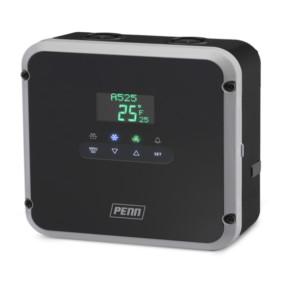
A52x Series Refrigeration Controller with Adaptive Defrost
Installation Instructions
A524/A525
IMPORTANT: Use of this product is subject to and constitutes your agreement to the End User License
Agreement set forth at www.johnsoncontrols.com/buildings/legal/digital Part No. 24-07664-03310
Application
IMPORTANT: Use this A52x Series Refrigeration Controller only as an operating control. Where failure or
malfunction of the A52x Controller could lead to personal injury or property damage to the controlled equipment
or other property, additional precautions must be designed into the control system. Incorporate and maintain
other devices, such as supervisory or alarm systems or safety or limit controls, intended to warn of or protect
against failure or malfunction of the A52x Controller.
IMPORTANT : Utiliser ce A52x Series Refrigeration Controller uniquement en tant que dispositif de contrôle de
fonctionnement. Lorsqu'une défaillance ou un dysfonctionnement du A52x Régulateur risque de provoquer des
blessures ou d'endommager l'équipement contrôlé ou un autre équipement, la conception du système de
contrôle doit intégrer des dispositifs de protection supplémentaires. Veiller dans ce cas à intégrer de façon
permanente d'autres dispositifs, tels que des systèmes de supervision ou d'alarme, ou des dispositifs de
sécurité ou de limitation, ayant une fonction d'avertissement ou de protection en cas de défaillance ou de
dysfonctionnement du A52x Régulateur.
The A52x Series Refrigeration Controller with Adaptive Defrost provides refrigerated space control and defrost
control for medium and low temperature refrigeration applications.
The A525 Controller has five integral line-voltage, dry-contact relays to control the compressor, defrost heater or
solenoid, evaporator fans, and user-provided alarm devices. The controller can control resistive heat, hot-gas
bypass, or passive defrost. The controller can also control two-speed evaporator fans. The A524 Controller has
four integral line-voltage relays and controls the same devices as the A525 Controller. The LO-SPD AUX relay is
not available on the A524 Controller, which controls a single speed evaporator fan only.
The adaptive defrost feature allows the controller to adjust the defrost schedule to the minimum number of defrost
intervals required to maintain peak efficiency, save energy, and maintain consistent space temperature. The A52x
Controller has an IP65 enclosure with holes in the enclosure base for wall-surface mounting. An optional DIN rail
mount kit (Part No. BKT524-1K) is also available.
Refer to the A52x Series Refrigeration Controller with Adaptive Defrost Technical Bulletin (LIT-12012405) for more
details on setting up, operating, and troubleshooting the A52x Controller. You can access and download the A52x
Controller Technical Bulletin from QuickLIT.
Parts Included
Each A52x Series Controller includes two Johnson Controls/PENN® A99B Series Temperature Sensors. See
Sensor Wiring on page 6, Table 12 on page 11, and refer to the A99B Series Temperature Sensors Product/
Technical Bulletin (LIT-125186) for more detailed installation procedures and technical specifications.
A52x Series Refrigeration Controller with Adaptive Defrost Installation Instructions
Refer to the
QuickLIT website
1
Part No. 24-07664-03310 Rev. C
Issued April 2018
for the most up-to-date version of this document.
Advertisement
Table of Contents

Related Manuals for Penn A52 Series


Summary of Contents for Penn A52 Series
- Page 1 Controller Technical Bulletin from QuickLIT. Parts Included Each A52x Series Controller includes two Johnson Controls/PENN® A99B Series Temperature Sensors. See Sensor Wiring on page 6, Table 12 on page 11, and refer to the A99B Series Temperature Sensors Product/ Technical Bulletin (LIT-125186) for more detailed installation procedures and technical specifications.
-
Page 2: Mounting Considerations
Dimensions Figure 1: A52x Refrigeration Control with IP65 Enclosure Dimensions, mm (in.) Mounting Mounting Considerations Observe the following A52x Controller location and mounting guidelines: • Mount the controller on a flat surface. • Ensure that the mounting surface can support the controller assembly, mounting hardware, and any user-supplied panel or enclosure. -
Page 3: Wall Mounting
Figure 2: A52x Refrigeration Control Wall-Surface Mounting Wall Mounting Table 1: A52x Refrigeration Control Wall-Surface Mounting Callout Description Spring-loaded cover screw on the controller cover Keyhole slot on the rear of the enclosure base Mounting screw hole on the enclosure base To mount the A52x Controller on a wall or other flat surface, complete the following steps: 1. -
Page 4: Din Rail Mounting
DIN Rail Mounting An optional DIN Rail mount kit (Product Code Number, BKT524-1K) is available for the A52x Controller. The DIN rail clip assembly attaches to the five holes on the back of the enclosure base. Refer to the installation instructions included with the DIN rail kit for DIN rail mounting procedures. -
Page 5: Low Voltage Wiring
Risque de décharge électrique. Débrancher ou isoler toute alimentation avant de réaliser un branchement électrique. Plusieurs isolations et débranchements sont peut-être nécessaires pour-couper entièrement l'alimentation de l'équipement. Tout contact avec des composants conducteurs de tensions dangereuses risque d'entraîner une décharge électrique et de provoquer des blessures graves, voire mortelles. -
Page 6: Sensor Wiring
Table 2: A52x Controller Low-Voltage Terminal Blocks, Terminals, and Wire Sizes Terminal Terminal Description, Function, and Requirements Recommended Block Label Label Wire Sizes RS485 The RS485 Modbus communications terminal block provides a 0.20 to 0.30 mm MODBUS restricted connection to the Modbus connections on an optional (26 to 22 AWG) Precision Superheat Controller (PSHC). -
Page 7: High-Voltage Wiring
Table 3: Maximum Recommended Sensor Cable Lengths and Wire Sizes Wire Gauge Maximum Sensor Cable Length 150 m (500 ft) 1.3 mm (16 AWG) 100 m (300 ft) 0.82 mm (18 AWG) 60 m (200 ft) 0.52 mm (20 AWG) 40 m (125 ft) 0.33 mm (22 AWG) -
Page 8: Relay Electrical Ratings
Table 4: A52x Controller High-Voltage Terminal Blocks, Terminals, and Wire Sizes Terminal Terminal Description, Function, and Requirements Recommended Block Label Voltages Wire Sizes 90-240 VAC Two terminals for supply power connection to the A525 Controller. 0.75 to 2.50 mm Requires 90 to 240 VAC; 15 VA, (0.25 A maximum). (18 to 14 AWG) L2/N Earth ground connection terminal... -
Page 9: Repair Information
Do not attempt to repair the A52x Controller. In case of a defective or improperly functioning controller, contact your nearest authorized Johnson Controls/PENN Distributor or Sales Representative. When contacting your Johnson Controls/PENN Distributor, have the model number of the controller available. This number can be found on the label inside the cover of the controller. -
Page 10: Ordering Information
Table 10 on page 10 contains information about the A52x Controller accessories. For more information about A99B Temperature Sensors, refer to the A99B Series Temperature Sensors Product/Technical Bulletin (LIT-125186) or contact your nearest Johnson Controls/PENN distributor or sales representative. Table 10: A52x Controller Accessories... - Page 11 Table 11: UL Conformity Declaration Information Information Description Purpose of Control Sensing control/operating control Construction of Control Electronic independently mounted control Number of Cycles Compressor relay: 100,000 cycles Defrost relay: 30,000 cycles Evaporator fan relays: 30,000 cycles Alarm relay: 8,000 cycles Method of Mounting Control Four mounting screws or optional DIN rail mounting kit Type 1C or Type 2C Action...
-
Page 12: North American Emissions Compliance
Building Technologies & Solutions 507 E. Michigan Street, Milwaukee, WI 53202 ® Johnson Controls and PENN are registered trademarks of Johnson Controls in the United States of America and/or other countries. All other trademarks used herein are the property of their respective owners. © Copyright 2018 by Johnson Controls. All rights reserved.
Need help?
Do you have a question about the A52 Series and is the answer not in the manual?
Questions and answers